0086-577-67316655
fyv@fyvvalve.com
+8613588924788
Fangyuan Industrial Park, Anfeng Industrial Zone. Obei and Wenzhou, Zhejiang. China.
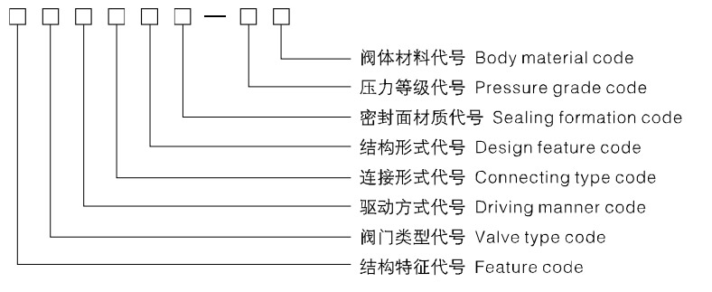
●Feature code: Body, bonnet bolt-jointed structure (default) Hs-body, bonnet welded structure Ps-pressure sealed structure
FL-Reduce expenditure and put emptily T-The valve is one set of types(valve one) K-Antisulphur model
●Valve type code:J-Globe valve
●Driving manner code: 4--Spur gear transmission 5-Bevel gear transmission 6-Air driving 6s-Take pneumatically manually
7-Hydrodynamic driving 9-Electric driving 9B--Explosion electric driving (Hand wheel driving omitted)
●Connecting type code:1-Interior whorl 2--Other whorl 4-Flange 6-Welding 8-Bear and insert welding
●Design feature code:1—Straight general formula 4—Angle type
●Sealing formation code:Y—Hard alloy H—Alloy steel D-Nitriding steel F—Intensified polytetrafluoroethylene(PTPE) X-Rubber
●Pressure grade code: The 10 times of the nominal pressure MPa, pound grade io practical number
●R-CF8M、ZG1Cr18Ni12Mo2Ti S-CF3 L-CF3M F-LCB N-LC3
●Body material code: (1) Cast the valve body: C-WCB I-WC6、ZG1Cr5Mo V-WC9、ZG20CrMoV P—CF8、ZG1Cr18Ni9Ti
R-CF8M、ZG1Cr18Ni12Mo2Ti S-CF3 L-CF3M F—LCB N—LC3
(2) Forge the valve body: C-A105 E-LF2 A-F11 V-F22 P—F304 R-F316 S-F304L L-F316L
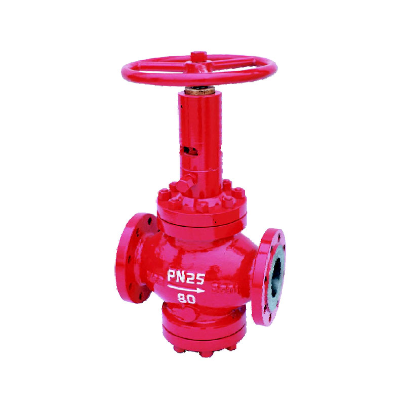
1. This valve is a brand-new throttle, stop and emptying product, uses a cage-like puzzle palace throttle and features a multiple-stage throttle effect, a notable throttle effect, a reliable seal and easy operation and maintenance.
2. The valve uses hard and soft two seals to get it reliably sealed, the carbide alloy sealing face becomes more resisting to the gas-flow erosion and more wearable and the dual-seal can realize nulleak under the high pressure gas medium, leaving along duration of the valve.
3. The sealing face of the seat ring uses a taper seal, benefit to the self-clean of the dirt absorbed onto the face.
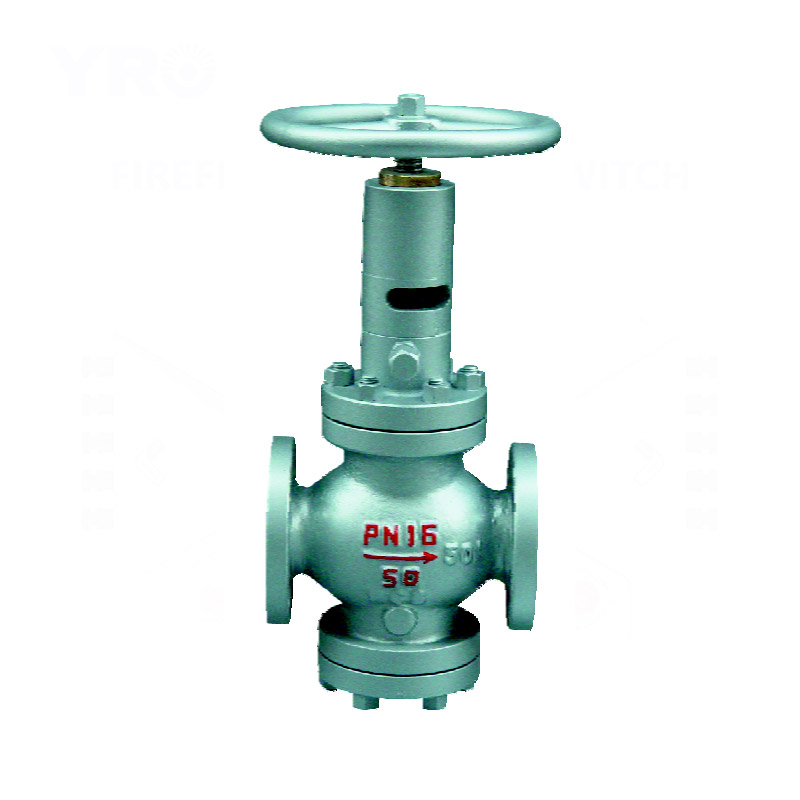
4. A balancing hole and a piston type seal are set on the valve's disc, making sure of a stable operation, light and flexible open-close and a small open-close torque.
5. The packing uses a V-type packing structure with self-seal ability, without need to adjust and with both open and close extremely light. An assisting sealing grease injector is set in the packing place to have its sealing performance reliable.
6. The valve can be on-line repaired and replacement of the packing etc. series easily-worn-out parts can be done with a pressure with the pipeline.
7. A bigger sewage removing hole is set on the botom of the valve, it can be opened when necessary to clean up the dirt inside of the valve.
8. There is O-seal ring on the outer circle of the sewage valve's disc,it features self-clean and self-seal function at open-close and throttle and pressure reduction function at sewage removal.
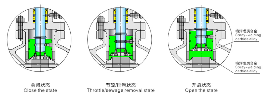
1. Constant close state: the hard seal pair of the floating disc presses on the convex desk of the seat ring to form the first hard seal and, in the meantime, the soft seal inlaid onto the disc is tightly against on the end-face of the seat ring to form the second seal, this dual-seal structure ensures nulleak of the valve and, plus the balancing hole on the disc, the disc is subjected to a smaller effort during open and close of the valve and a smaller moment is made available for the valve to open and close.
2. Throttle and sewage removal state: when the disc seal pair goes away from the seat ring, the balancing hole set on the disc Imakes the valve extremely easily opened and closed. After the valve is opened, the medium and the foreign matters go through the valve sleeve and the seat ring together and both throttle and sewage removal are realized. The sealing faces of both disc and seat ring use the inclination of the sleeve pad to change the medium's flowing direction and feature self-clean function so as to have the seal pair without foreign matters.
3. Closed state: when the valve is closed after the medium in the pipeline is drained out, the medium goes into the seat ring's channel through the inclination of the sleeve pad, the fluid resistance coefficient increases, the flow rate becomes quicker, the linclination changes the medium's flowing direction to produce eddy. The radial force of the medium on the end-face of the seat ring increases to carry out the blowing on the seal of the seat ring. When the disc seal pair is close to the seat ring, the fit interval between the sleeve pad and the seat ring's channel resists the bigger grain medium to flow into the seal pair, plus the further increased flow rate and the lateral blowing by the medium, the foreign matters with the seal pair has been completely cleaned when the valve is closed so as to ensure the sealing performance of the valve after sewage removal, further ensure null leak from the seal after sewage removal, thus greatly enhancing the capacity and extending the duration.
| Pressure | Testing pressure at constant temperature (Mpa) | Applicable temperature | Applicable medium | |||||||
| Shell | Seal | Have and seal | Low pressure air tightness | G type | D type | Ordinary | Sulphur resisting type | Ordinary | ||
| (MPa) Nominal rating pressure (PN) |
1.6 | 2.4 | 1.76 | 1.76 | 0.6 | -29~250 | -45~121 | -29~121 | Medium containing H₂S and CO₂ > 500mg/m³ |
Petroleum, natural gas, water,etc. |
| 2.5 | 3.8 | 2.75 | 2.75 | 0.6 | ||||||
| 4.0 | 6.0 | 4.4 | 4.4 | 0.6 | ||||||
| 6.4 | 9.6 | 7.04 | 7.04 | 0.6 | ||||||
| 10.0 | 15.0 | 11.0 | 11.0 | 0.6 | ||||||
| 16.0 | 24.0 | 17.6 | 17.6 | 0.6 | ||||||
| Design standard | GB/T12235 | |
| Face to face | Flanged ends | GB/T12221 |
| Welded connection | GB/T15188.1 | |
| Flanged ends | JB/T79、GB/T9113 | |
| Butt-welding ends | GB/T12224 | |
| Test& inspection | JB/T9092 | |
Notes: The sizes of valve connecting flange and butt-welding terminas can be designed according to customer's requirement.
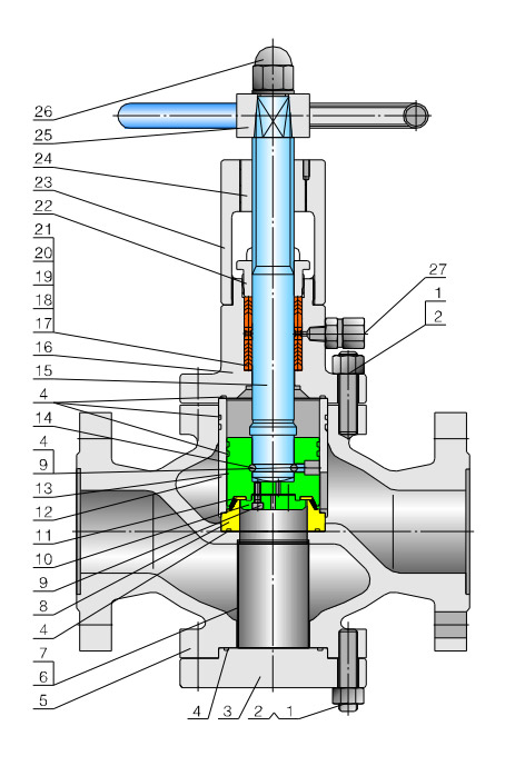 |
NO. | Part name | Material |
| 1 | Stud | 35CrMo | |
| 2 | Nut | 35 | |
| 3 | Bottom covering | 20 | |
| 4 | O-Ring | NBR | |
| 5 | Body | WCB | |
| 6 | Blowdown set | 1Cr18Ni9 | |
| 7 | Filter screen | 1Cr18Ni9 | |
| 8 | Seat | 20+Ni45 | |
| 9 | Socket head cap round-stud screw | 35 | |
| 10 | Pressing plate | 20 | |
| 11 | Seal ring | NBR | |
| 12 | Core set | 20+ENP | |
| 13 | Disc | 2Cr13+Ni60 | |
| 14 | Steel ball | Gcr15 | |
| 15 | Stem | 2Cr13 | |
| 16 | Bonnet | 25 | |
| 17 | Put the packing cushion | 1Cr13 | |
| 18 | Middle packing | PTFE | |
| 19 | Middle packing | NBR | |
| 20 | Have thepacking cushion | 1Cr13 | |
| 21 | Spacingring | PTFE | |
| 22 | Packing gland | 45 | |
| 23 | Yoke | WCB | |
| 24 | Valve stem nut | ZQAL9-4 | |
| 25 | Handwheel | 20 | |
| 26 | Nut | 35 | |
| 27 | Fat valve of the note | 25+zinc-plated(package) |
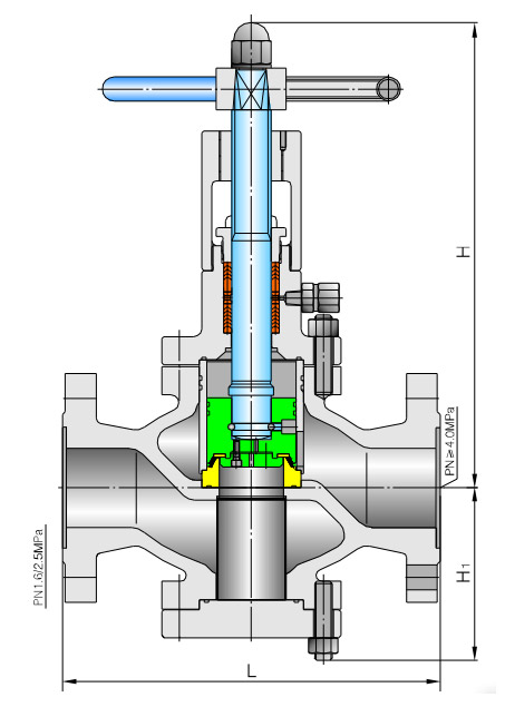
Model:(K)TP41Y
| PN (MPa) |
DN (mm) |
Dimensions (mm) | Weight (kg) |
|||
| L | H | H₁ | D₀ | |||
| 1.6 | 25 | 216 | 243 | 86 | 180 | 18 |
| 40 | 230 | 265 | 108 | 250 | 25 | |
| 50 | 230 | 346 | 115 | 250 | 28 | |
| 80 | 310 | 409 | 146 | 300 | 53 | |
| 100 | 350 | 433 | 163 | 300 | 62 | |
| 150 | 480 | 521 | 202 | 350 | 128 | |
| 200 | 600 | 594 | 292 | 350 | 168 | |
| 250 | 730 | 621 | 355 | 400 | 289 | |
| 2.5 | 25 | 216 | 243 | 86 | 180 | 18 |
| 40 | 230 | 265 | 108 | 250 | 25 | |
| 50 | 230 | 346 | 115 | 250 | 28 | |
| 80 | 310 | 409 | 146 | 300 | 57 | |
| 100 | 350 | 433 | 163 | 300 | 69 | |
| 150 | 480 | 521 | 202 | 350 | 145 | |
| 200 | 600 | 594 | 292 | 350 | 188 | |
| 250 | 730 | 621 | 355 | 400 | 315 | |
| 4 | 25 | 216 | 243 | 86 | 180 | 21 |
| 40 | 230 | 265 | 108 | 250 | 31 | |
| 50 | 230 | 346 | 115 | 250 | 35 | |
| 80 | 310 | 409 | 146 | 300 | 70 | |
| 100 | 350 | 433 | 163 | 300 | 85 | |
| 150 | 480 | 521 | 202 | 350 | 172 | |
| 200 | 600 | 594 | 292 | 350 | 219 | |
| 250 | 730 | 621 | 355 | 400 | 378 | |
| PN (MPa) |
DN (mm) |
Dimensions (mm) | Weight (kg) |
|||
| L | H | H₁ | D₀ | |||
| 6.4 | 25 | 216 | 243 | 86 | 180 | 21 |
| 40 | 230 | 265 | 108 | 250 | 37 | |
| 50 | 230 | 346 | 115 | 250 | 42 | |
| 80 | 310 | 409 | 146 | 300 | 84 | |
| 100 | 350 | 433 | 163 | 300 | 100 | |
| 150 | 480 | 521 | 202 | 350 | 208 | |
| 200 | 600 | 594 | 292 | 350 | 265 | |
| 250 | 730 | 621 | 355 | 400 | 452 | |
| 10.0 | 25 | 230 | 245 | 78 | 200 | 30 |
| 40 | 260 | 265 | 106 | 250 | 44 | |
| 50 | 300 | 287 | 110 | 300 | 58 | |
| 80 | 380 | 409 | 152 | 350 | 98 | |
| 100 | 430 | 433 | 169 | 350 | 125 | |
| 150 | 559 | 531 | 225 | 400 | 245 | |
| 200 | 660 | 709 | 321 | 500 | 316 | |
| 250 | 787 | 817 | 399 | 500 | 540 | |
| 16.0 | 25 | 230 | 215 | 78 | 200 | 36 |
| 40 | 260 | 265 | 105 | 250 | 54 | |
| 50 | 300 | 237 | 110 | 300 | 69 | |
| 80 | 390 | 414 | 155 | 350 | 120 | |
| 100 | 450 | 440 | 175 | 350 | 150 | |
The increasing popularity of IoT devices has driven the demand for industrial valves. The integration of IoT sensors in industrial valves enables real-time monitorin...
A gate valve is an opening and closing component, and its movement direction is perpendicular to the fluid direction. A gate valve can only be fully opened and fully...
Ball valve, the opening and closing element (ball) is driven by the valve stem and rotates around the axis of the ball valve. It can also be used for fluid regulatio...