0086-577-67316655
fyv@fyvvalve.com
+8613588924788
Fangyuan Industrial Park, Anfeng Industrial Zone. Obei and Wenzhou, Zhejiang. China.
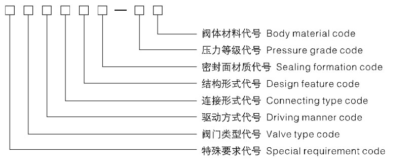
●Special requirement code: Body, bonnet bolt-jointed structure (default) Hs-body, bonnet welded structure
Ps-pressure sealed structure D-low temperature valve B-bellows valve E-body extended-end valve
●Valve type code: Z-Gate valve
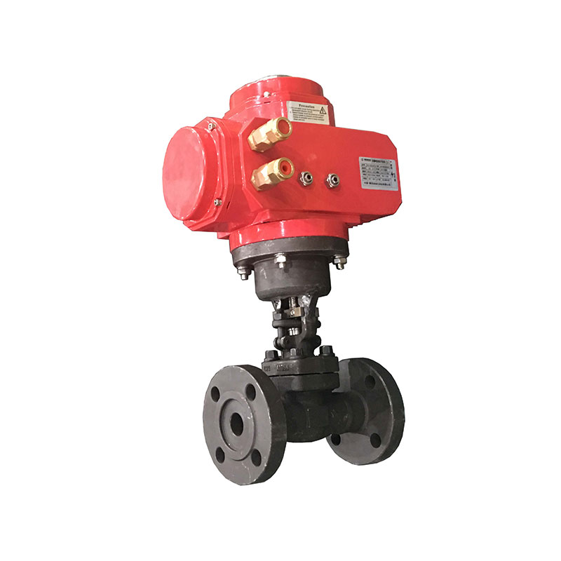
●Driving manner code: 4-Spur gear transmission 5-Bevel gear transmission 6-Air driving 6s-Take pneumatically manually
7-Hydrodynamic driving 9-Electric driving (Hand wheel driving omitted) 9--Explosion electric driving
●Connecting type code: 1-Interior whorl 2-Other whorl 4-Flange 6-Welding 8--Bear and insert welding
●Design feature code: 1-Single-disc 4-Double-disc
●Sealing formation code: Y-Hard alloy H-Alloy steel
●Pressure grade code: The 10 times of the nominal pressure MPa, pound grade io practical number
●Body material code: (1)Cast the valve body: C-WCB I-WC6、ZG1Cr5Mo V-WC9、ZG20CrMoV P-CF8、ZG1Cr18Ni9Ti
R-CF8M、ZG1Cr18Ni12Mo2Ti S-CF3 L-CF3M F-LCB N-LC3
(2)Forge thevalve body: C-A105 E-LF2 A-F11 V-F22 P-F304 R-F316 S-F304L L-F316L
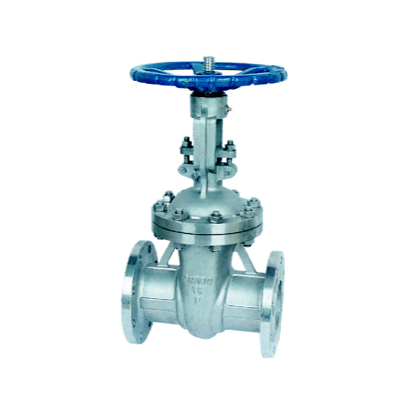
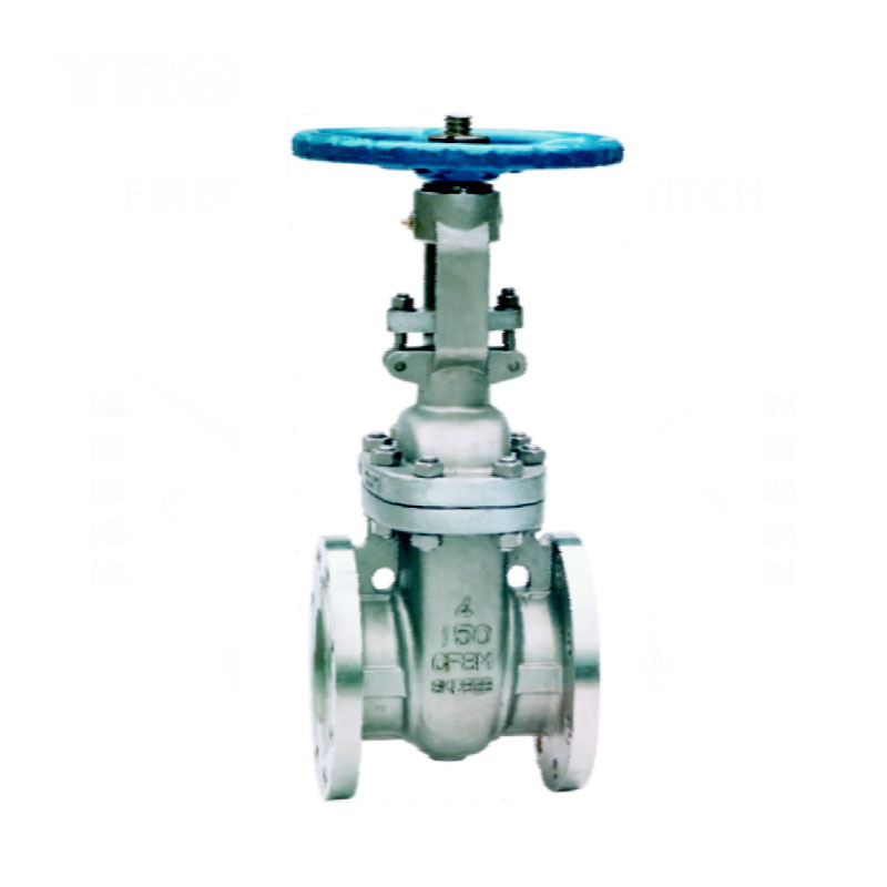
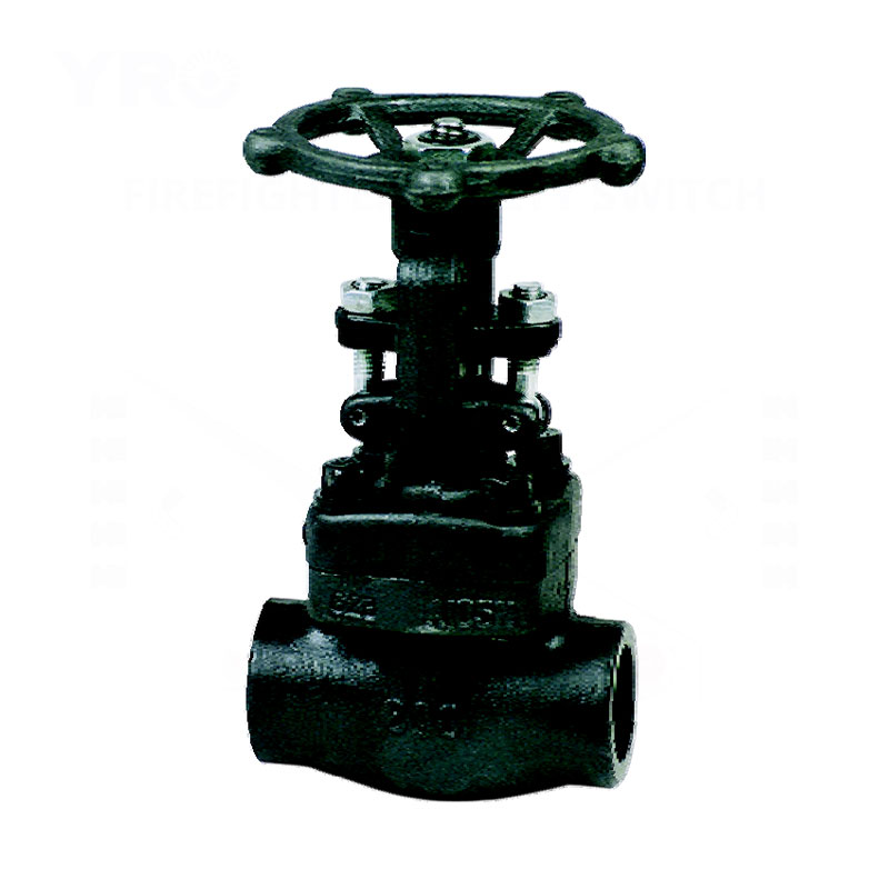
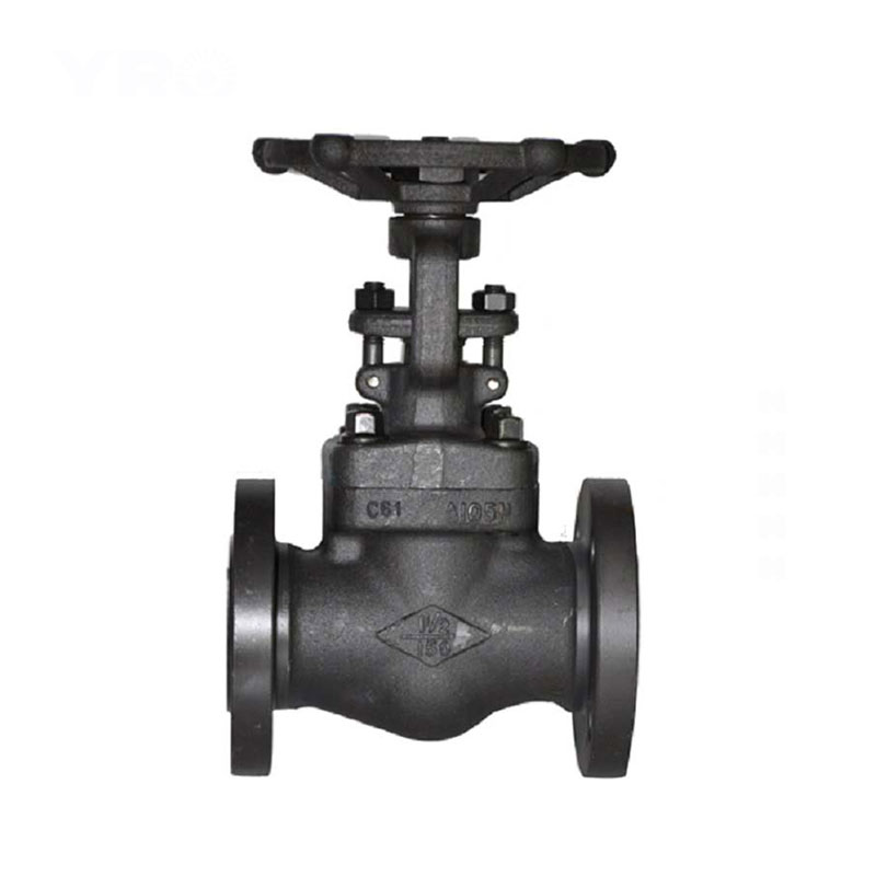
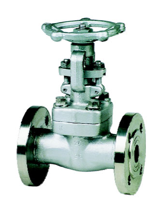
Flanged ends cast steel gate valve are used to cut or connect the pipe media under nominal pressure between PN1.6~42.0MPa (Class150~2500), working temperatures <600℃. in oil industry, chemical industry, fossil-fired power plants.
The main structure features include:
1. Both design and manufacture are carried out strictly following GB/T12234, API600 and API602. The products feature a reasonable structure, reliable seal, good performance and nice modeling.
2. Co hard alloy welded sealing surface, which is wearing resistant, erosion proof, abrasion proof and long-lived.
3. The surface and the adjusting media of the valve shaft are nitrogenized so that it is erosion and abrasion resistant.
4. PN>15.oMpa (class9oo), the middle cavity uses a self-tightening sealing structure to have the sealing performance reinforced along with the pressure rise so as to ensure the sealing performance.
5. There is no backward sealing structure in the valve, so the sealing id reliable.
6. The material of the filling and the flange size can be chosen and matched according to the applications and the requirements of the use's. That can satisfies all kinds of working requirements.
| Serial models | (Hs、Ps)Z11H、(Hs、Ps)Z11Y、(Ps)Z41H、(Ps)Z41Y、(Ps)Z441H、(Ps)Z441Y、 (Ps)Z541H、(Ps)Z541Y、(Ps)Z941H、(Ps)Z941Y |
|||
| Pressure grade range | PN1.6~42.0MPa(Class150~2500) | |||
| Drift diameter range | DN15~1000mm(1"~40") | |||
| Driving manner | Hand wheel driving | Gear driving and electric driving | ||
| Scope of application | Class150~300 (PN1.6~4.0) |
Class400~600 (PN6.4~10.0) |
Class900~2500 (PN15.0~42.0) |
2"~40" (DN50~1000mm) |
| ¹/₂"~24" (DN15~600mm) |
¹/₂"~12" (DN15~300mm) |
¹/₂"~10" (DN15~250mm) |
||
| Pressure | Testing pressure at constant temperature (Mpa) | Applicable temperature | Applicable medium | |||
| The shell testing | Seal and test | Have and seal testing | ||||
| (MPa) Nominal rating pressure (PN) |
1.6 | 2.4 | 1.76 | 1.76 | -196~600℃ | Water,oil,steam,etc. |
| 2.5 | 3.8 | 2.75 | 2.75 | |||
| 4.0 | 6.0 | 4.4 | 4.4 | |||
| 6.4 | 9.6 | 7.04 | 7.04 | |||
| 10.0 | 15.0 | 11.0 | 11.0 | |||
| 16.0 | 24.0 | 17.6 | 17.6 | |||
| 25.0 | 37.5 | 27.5 | 27.5 | |||
| (Lb) Pound grade (Class) |
150 | 3.0 | 2.2 | 2.2 | ||
| 300 | 7.5 | 5.5 | 5.5 | |||
| 600 | 15.0 | 11.0 | 11.0 | |||
| 900 | 22.5 | 16.5 | 16.5 | |||
| 1500 | 37.5 | 27.5 | 27.5 | |||
| 2500 | 63.0 | 46.2 | 46.2 | |||
 |
Structural formation | Bolt (Weld)-jointed bonnet outside stem yoke structure |
| Driving manner | Hand-operated | |
| Design standard | API602、BS5352 | |
| Face to face | ASME B16.10 | |
| Flanged ends | ASME B16.5 | |
| Test & inspection | API 598 |
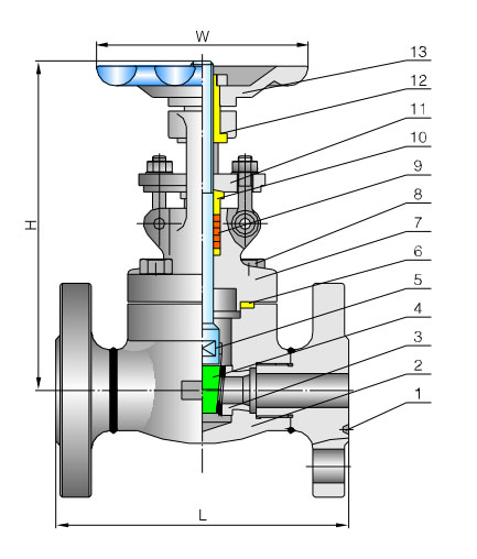 |
No. | Part name | Material |
| 1 | Flange | ASTM A105 ASTM A182-F11、F22、F5、F9 ASTM A182-F304、F316、F321、F304L、F316L |
|
| 2 | Body | ASTM A105 ASTM A182-F11、F22、F5、F9 ASTM A182-F304、F316、F321、F304L、F316L |
|
| 3 | Seat | ASTM A105 ASTM A182-F11、F22、F5、F9 ASTM A182-F304、F316、F321、F304L、F316L |
|
| 4 | Gate disc | ASTM A105 ASTM A182-F11、F22、F5、F9 ASTM A182-F304、F316、F321、F304L、F316L |
|
| 5 | Stem | ASTM A182Gr.F6a、ASTM A182F22 ASTM A182-F304、F316、F321、F304L、F316L |
|
| 6 | Gasket | Graphite & stainless steel | |
| 7 | Bonnet | ASTM A105 ASTM A182-F11、F22、F5、F9 ASTM A182-F304、F316、F321、F304L、F316L |
|
| 8 | Bolt | ASTM A193-B7、A320-B8、F321、F304L、F316L | |
| 9 | Packing | Graphite | |
| 10 | Packing press-sleeve | ASTM A182Gr.F6a、ASTMA182F22 ASTM A182-F304、F316、F321、F304L、F316L |
|
| 11 | Packing gland | ASTM A216-WCB ASTM A351-CF8、CF8M、CF8C、CF3、CF3M |
|
| 12 | Valve stem nut | Copper alloy | |
| 13 | Handwheel | ASTM A47-32510 |
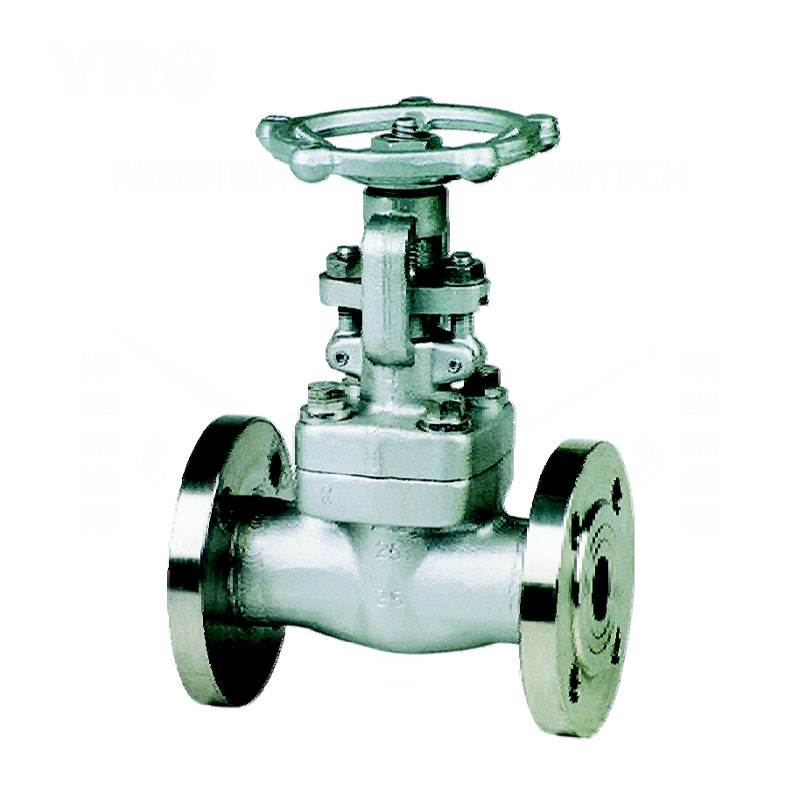
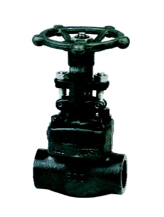
Model: (Hs、Ps)Z11H、(Hs、Ps)Z11Y、(Hs、Ps)Z41H、(Hs、Ps)Z41Y、(Hs、Ps)Z61H、(Hs、Ps)Z61Y
| Class | 150 | 300 | 600 | |||||||||||||
| DN | L | H① | W | Weight (kg) |
L | H① | W | Weight (kg) |
L | H① | W | Weight (kg) |
||||
| mm | in | RF | RTJ | RF | RTJ | RF | RTJ | |||||||||
| 15 | ¹/₂ | 108 | 119 | 160 | 100 | 4.5 | 140 | 151 | 160 | 100 | 4.8 | 165 | 163.5 | 160 | 100 | 5.8 |
| 20 | ³/₄ | 117.5 | 130 | 165 | 100 | 5.1 | 152.5 | 165 | 165 | 100 | 6.2 | 190.5 | 190.5 | 165 | 100 | 7.5 |
| 25 | 1 | 127 | 140 | 192 | 125 | 8.5 | 165 | 178 | 192 | 125 | 9.4 | 216 | 216 | 192 | 125 | 10.3 |
| 32 | 1 ¹/₄ | 140 | 153 | 220 | 160 | 11.5 | 178 | 191 | 220 | 160 | 14.2 | 229 | 229 | 220 | 160 | 16.3 |
| 40 | 1 ¹/₂ | 165 | 178 | 245 | 160 | 11.2 | 190.5 | 203 | 245 | 160 | 15.5 | 241 | 241 | 245 | 160 | 17.5 |
| 50 | 2 | 216 | 216 | 285 | 180 | 20 | 216 | 232 | 285 | 180 | 23.5 | 292 | 295 | 285 | 180 | 28.4 |
Notes: H represents the height in full opening condition of valve.
 |
Structural formation | Bolt (Weld)-jointed bonnet outside stem yoke structure |
| Driving manner | Hand-operated | |
| Design standard | API602、BS5352 | |
| Thread ends | ASME B1.20.1 | |
| Socket welded ends | ASME B16.11 | |
| Test & inspection | API 598 |
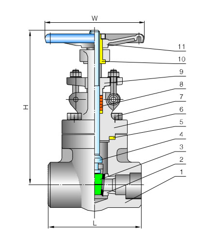 |
No. | Part name | Material |
| 1 | Body | ASTM A105 ASTM A182-F11、F22、F5、F9 ASTM A182-F304、F316、F321、F304L、F316L |
|
| 2 | Seat | ASTM A105 ASTM A182-F11、F22、F5、F9 ASTM A182-F304、F316、F321、F304L、F316L |
|
| 3 | Gate disc | ASTM A105 ASTM A182-F11、F22、F5、F9 ASTM A182-F304、F316、F321、F304L、F316L |
|
| 4 | Stem | ASTM A182Gr.F6a、ASTM A182F22 ASTM A182-F304、F316、F321、F304L、F316L |
|
| 5 | Gasket | Graphite & stainless steel | |
| 6 | Bonnet | ASTM A105 ASTM A182-F11、F22、F5、F9 ASTM A182-F304、F316、F321、F304L、F316L |
|
| 7 | Bolt | ASTM A193-B7、A320-B8、F321、F304L、F316L | |
| 8 | Packing | Graphite | |
| 9 | Packing gland | ASTM A216-WCB ASTM A351-CF8、CF8M、CF8C、CF3、CF3M |
|
| 10 | Valve stem nut | Copper alloy | |
| 11 | Handwheel | ASTM A47-32510 |
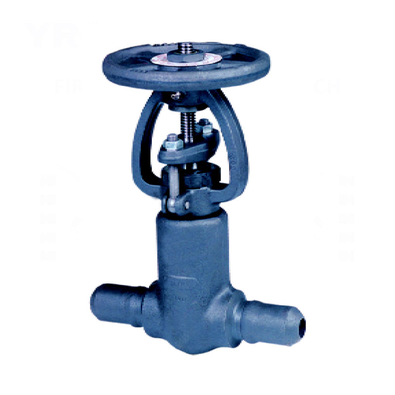
Model: (Hs、Ps)Z11H、(Hs、Ps)Z11Y、(Hs、Ps)Z41H、(Hs、Ps)Z41Y、(Hs、Ps)Z61H、(Hs、Ps)Z61Y
| Class | 800 | 1500 | |||||||||
| DN | Dimensions (mm) | Weight (kg) |
Dimensions (mm) | Weight (kg) |
|||||||
| Reduced bore | Full bore | L | H① | W | L | H① | W | ||||
| mm | in | mm | in | ||||||||
| 15 | ¹/₂ | 10 | ³/₈ | 80 | 160 | 100 | 1.9 | 111 | 203 | 125 | 4.2 |
| 20 | ³/₄ | 15 | ¹/₂ | 92 | 165 | 100 | 2.1 | 111 | 203 | 125 | 4.6 |
| 25 | 1 | 20 | ³/₄ | 111 | 192 | 125 | 3.2 | 115 | 216 | 160 | 6.2 |
| 32 | 1 ¹/₄ | 25 | 1 | 120 | 220 | 160 | 6.9 | 120 | 235 | 160 | 8.2 |
| 40 | 1 ¹/₂ | 32 | 1 ¹/₄ | 120 | 245 | 160 | 6.9 | 140 | 275 | 180 | 11.0 |
| 50 | 2 | 40 | 1 ¹/₂ | 140 | 285 | 180 | 10.4 | 162 | 320 | 200 | 15.8 |
| 50 | 2 | 172 | 392 | 200 | 15.8 | 180 | 368 | 250 | 24.5 | ||
Notes: H represents the height in full opening condition of valve.
 |
Structural formation | Bolt (Weld)-jointed bonnet outside stem yoke structure |
| Driving manner | Hand-operated | |
| Design standard | API602、BS5352 | |
| Thread ends | ASME B1.20.1 | |
| Socket welded ends | ASME B16.11 | |
| Test & inspection | API 598 |
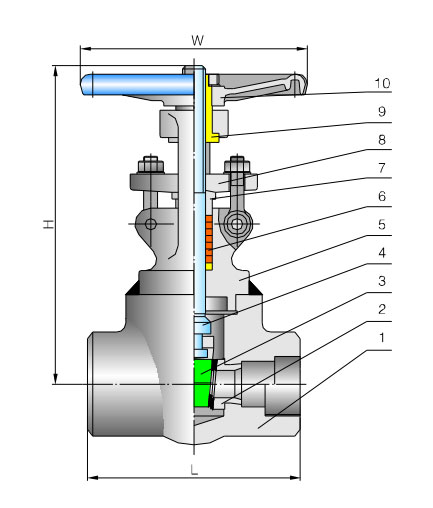 |
No. | Part name | Material |
| 1 | Body | ASTM A105 ASTM A182-F11、F22、F5、F9 ASTM A182-F304、F316、F321、F304L、F316L |
|
| 2 | Seat | ASTM A105 ASTM A182-F11、F22、F5、F9 ASTM A182-F304、F316、F321、F304L、F316L |
|
| 3 | Wedge | ASTM A105 ASTM A182-F11、F22、F5、F9 ASTM A182-F304、F316、F321、F304L、F316L |
|
| 4 | Stem | ASTM A182Gr.F6a、ASTM A182F22 ASTM A182-F304、F316、F321、F304L、F316L |
|
| 5 | Bonnet | ASTM A105 ASTM A182-F11、F22、F5、F9 ASTM A182-F304、F316、F321、F304L、F316L |
|
| 6 | Packing | Graphite | |
| 7 | Packing press-sleeve | ASTM A182Gr.F6a、ASTM A182F22 ASTM A182-F304、F316、F321、F304L、F316L |
|
| 8 | Packing gland | ASTM A216-WCB ASTM A351-CF8、CF8M、CF8C、CF3、CF3M |
|
| 9 | Valve stem nut | Copper alloy | |
| 10 | Hand wheel | ASTM A47-32510 |
Model: (Hs、Ps)Z11H、(Hs、Ps)Z11Y、(Hs、Ps)Z41H、(Hs、Ps)Z41Y、(Hs、Ps)Z61H、(Hs、Ps)Z61Y
| Class | 2500 | ||||||
| DN | Dimensions (mm) | ||||||
| Reduced bore | Full bore | L | H① | W | Weight (kg) |
||
| mm | in | mm | in | ||||
| 15 | ¹/₂ | 10 | ³/₈ | 111 | 185 | 125 | 5.2 |
| 20 | ³/₄ | 15 | ¹/₂ | 127 | 215 | 140 | 5.5 |
| 25 | 1 | 20 | ³/₄ | 127 | 245 | 160 | 7.4 |
| 32 | 1 ¹/₄ | 25 | 1 | 127 | 276 | 160 | 9.5 |
| 40 | 1 ¹/₂ | 32 | 1 ¹/₄ | 140 | 276 | 180 | 9.8 |
| 50 | 2 | 40 | 1 ¹/₂ | 210 | 340 | 200 | 19.5 |
| 50 | 2 | 230 | 405 | 240 | 29 | ||
Notes: H represents the height in full opening condition of valve.
The increasing popularity of IoT devices has driven the demand for industrial valves. The integration of IoT sensors in industrial valves enables real-time monitorin...
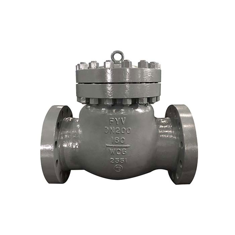
A gate valve is an opening and closing component, and its movement direction is perpendicular to the fluid direction. A gate valve can only be fully opened and fully...
Ball valve, the opening and closing element (ball) is driven by the valve stem and rotates around the axis of the ball valve. It can also be used for fluid regulatio...