0086-577-67316655
fyv@fyvvalve.com
+8613588924788
Fangyuan Industrial Park, Anfeng Industrial Zone. Obei and Wenzhou, Zhejiang. China.
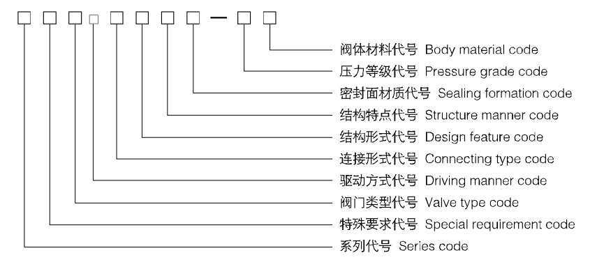
●Series code: The series code of our company is FY
●Special requirement code: K-Antisulphur model
●Valve type code: Z-Gate valve
●Driving manner code: 4-Spur gear transmission 5-Bevel gear transmission 9-Electric driving
9e-Explosion electric driving (Hand wheel driving omitted)
●Connecting type code: 4-The flange joining 6-To welding joining
●Design feature code: 7-Dark pole parallel single-disc
●Structure manner code: W-Non-diversion hole type (Diversion hole type omitted)
●Sealing formation code: F-Intensified polytetrafluoroethylene(PTFE)
●Pressure grade code: The 10 times of the nominal pressure MPa, pound grade io practical number
●Body material code: C-WCB P-CF8、ZG1Cr18Ni9Ti R-CF8M、ZG1Cr18Ni12Mo2Ti
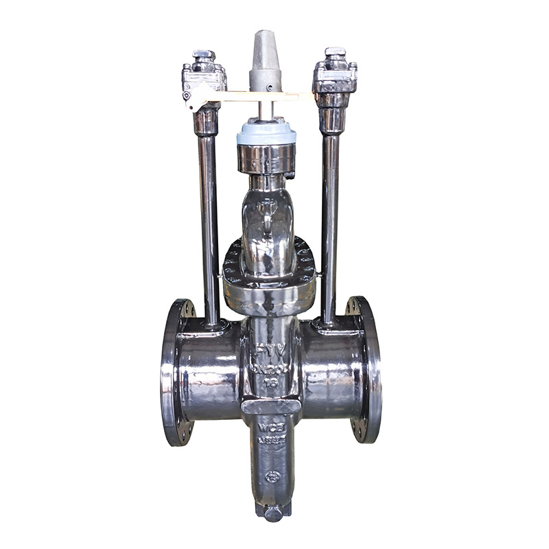
●Cast and weld two structures with the body
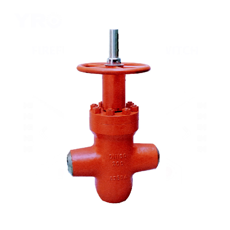
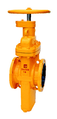
●The seat ring uses the floating seat ring structure with o-seal ring sealed and pre-tightening force applied to have inlet and outlet dual-way sealed; and the open-close moment with this structure is 1/2 that of the common valves only, able to lightly open and close valves.
●The seat ring uses the sealing face inlaid with PTFE, so has dual seals of PTFE to metal and metal to metal, the PTFE sealing face also acts as removing the dirt on the wedge disc.
●For the valve with the metal to metal seal, there is grease injector outside of it, grease gets into the sealing face through the injector and the seat ring to have the valve up to null leak.
●The wedge disc of the valve with flow guide hole is always fitted with the sealing face whether in full open or full close status to have the sealing face protected without being directly eroded by the medium so as to extend the duration.
●When fully opened, the valve's channel is smooth and linear, with an extremely small flow resisting coefficient and no pressure loss, and the pipeline can be cleaned with hair-ball through it.
●This valve uses the packing structure with the ability of self-seal, needs no constant adjustment, features very light open and close and a reliable seal. An assisting sealing grease injection structure is set in the packing to have the sealing performance absolutely reliable and get a true nulleak, settling the problem for the packing place of universal valves to be easiest leak outward.
●Automatic removal of the high pressure in the internal cavity when the valve is about to close (see the working principle diagram for the details) so as to ensure safety.
●Fully sealed structure leaves a good protective property, suitable for the requirement of 24-hour duty.
●An indication rod or viewing window is set with the valve to show the open-close condition.
Example1:FYZ47F-10C
Note: PN=1.oMpa, spur gear actuated,flange connected inside stem parallel type single-disc gate valve with flow guide hole, the body material is WCB and the sealing face material is reinforced PTFE.
Example2: FY(K)Z67F-16C
Note: PN=1.6Mpa, manually actuated, butt-weld connected, sulphur resisting inside stem parallel type single-disc gate valve with flow guide hole, the body material is WCB and the sealing face material is reinforced PTFE.
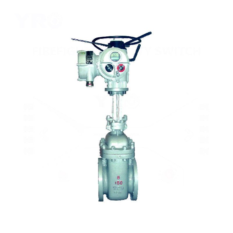
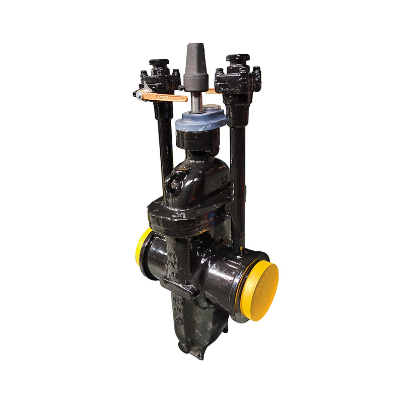
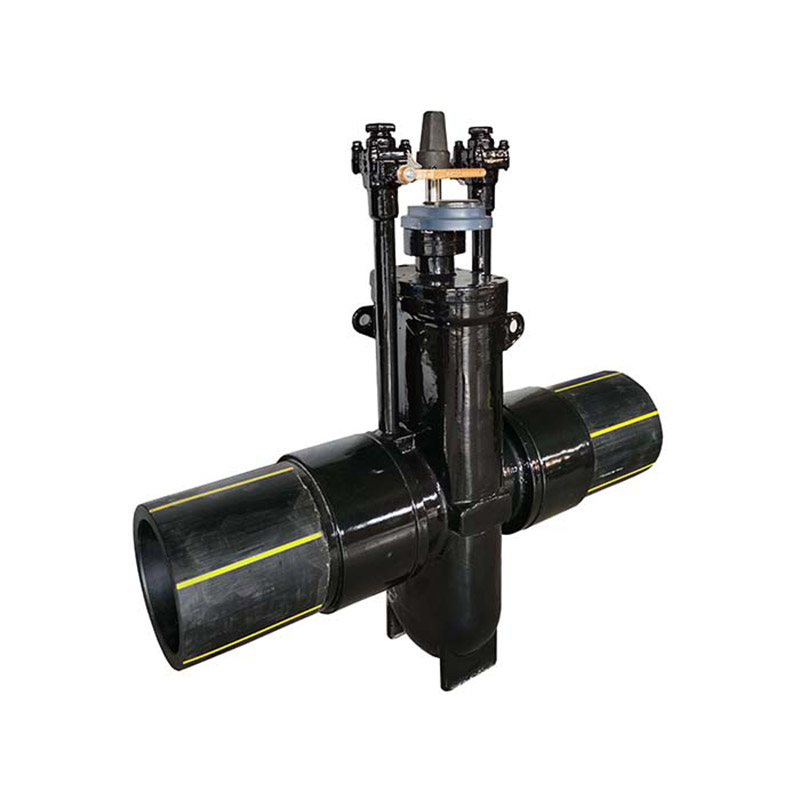
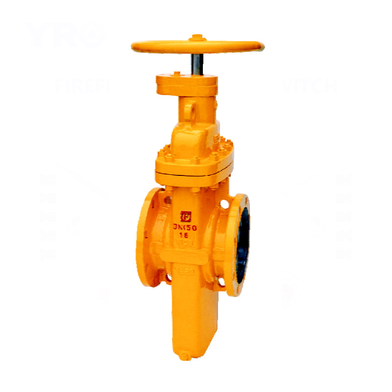
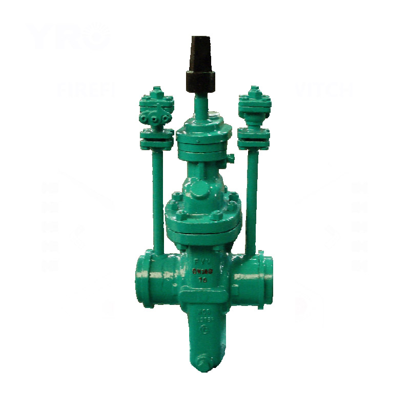
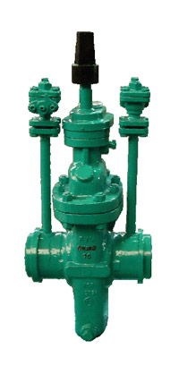
●The body uses a cast structure.
●The seat ring uses the floating seat ring structure with o-seal ring sealed and pre-tightening force applied to have inlet and outlet dual-way sealed; and the open-close moment with this structure is 1/2 that of the common valves only, able to lightly open and close valves.
●The seat ring uses the sealing face inlaid with PTFE, so has dual seals of PTFE to metal and metal to metal, the PTFE sealing face also acts as removing the dirt on the wedge disc.
●The wedge disc of the valve is always fitted with the sealing face whether in full open or full close status to have the sealing face protected without being directly eroded by the medium so as to extend the duration.
●When fully opened, the valve's channel is smooth and linear, with an extremely small flow resisting coefficient and no pressure loss, and the pipeline can be cleaned with hair-ball through it.
●Automatic removal of the high pressure in the internal cavity when the valve is about to close (see the working principle diagram for the details) so as to ensure safety.
●Use a sealed gear-driving open-close indicating mechanism, which is able to clearly show the open-close condition of the valve in a long term.
●The external surface of the directly built-in valve is corrosion resisting treated with epoxy coal bitumen and can be the same duration as the pipeline.
| Pressure | Testing pressure at constant temperature (Mpa) | Applicable temperature | Applicable medium | |||||
| The shell testing | The left sealing | Right sealing | Low pressure air tightness | Ordinary type | Antisulphur type | |||
| (MPa) Nominal rating pressure (PN) |
1.6 | 2.4 | 1.76 | 1.76 | 0.6 | -29~121℃ or upon the user requirement |
Petroleum, natural gas,water etc. non-corrosive media |
Petroleum,natural gas, water etc,containing H₂S, CO₂ corrosive media |
| 2.5 | 3.75 | 2.75 | 2.75 | 0.6 | ||||
| 4.0 | 6.0 | 4.4 | 4.4 | 0.6 | ||||
| 6.4 | 9.6 | 7.04 | 7.04 | 0.6 | ||||
| (Lb) Pound grade (Class) |
150 | 3.0 | 2.2 | 2.2 | 0.6 | |||
| 300 | 7.5 | 5.5 | 5.5 | 0.6 | ||||
| Serial models | FYZ47F、FYZ67F、FYZ447F、FYZ467F、FYZ547F、FYZ567F、FYZ9B47F、FYZ9B67F | ||
| Pressure grade range | PN0.6~6.4MPa (Class150~900) | ||
| Drift diameter range | DN25~1000mm(1"~40") | ||
| Driving manner | Hand wheel driving | Gear driving, air-operating, hydrodynamic driving and electric driving | |
| Scope of application | Class150~300 (PN1.6~4.0) |
Class400 (PN6.4) |
Class150~900 |
| 1"~40" (DN25~1000mm) |
1"~28" (DN25~700mm) |
1"~40" (DN25~1200mm) |
|
Note: Our company can provide products at customres'request.
 |
Design reference | GB | API | |
| Design standard | JB/T 5298 GB/T 19672 |
API 6D ASME B16.34 |
||
| Structural length | Flanged ends | GB/T 12221 GB/T 19672 JB/T 5298 |
API 6D ASME B16.10 |
|
| Welded connection | GB/T 15188.1 GB/T 19672 |
|||
| Flanged ends | GB/T 9113 JB/T 79 |
ASME B16.5 MSS SP44 |
||
| Butt-welding ends | GB/T 12224 | ASME B16.25 | ||
| Test & inspection | JB/T 9092 | API 6D API 598 |
||
Note: valve can be designed according to customer's requirement.
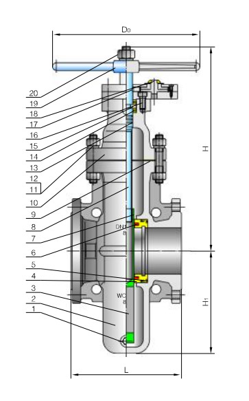 |
No. | Accessory name | Material |
| GB | |||
| 1 | Blow down stopple | 25 | |
| 2 | Body | WCB | |
| 3 | Gate disc | 16Mn+ENP | |
| 4 | Seat | 16Mn | |
| 5 | O-Ring | FPM | |
| 6 | Sealing ring | PTFE | |
| 7 | Valve stem nut | ZQAL9-4 | |
| 8 | Stem | 1Cr13 | |
| 9 | Packing | Graphite+1Cr18Ni9 | |
| 10 | Bonnet | WCB | |
| 11 | Stud | 35CrMo | |
| 12 | Nut | 45 | |
| 13 | O-Ring | FPM | |
| 14 | Bearing | Package | |
| 15 | To the ring of holding | 45 | |
| 16 | Six angle screws inside | 35 | |
| 17 | Key | 45 | |
| 18 | Switch indicator | PTFE+1Cr18Ni9 | |
| 19 | Hand wheel | Q235A | |
| 20 | Nut | 35 |
 |
Design reference | GB | API | |
| Design standard | JB/T 5298 GB/T 19672 |
API 6D ASME B16.34 |
||
| Structural length | Flanged ends | GB/T 12221 GB/T 19672 JB/T 5298 |
API 6D ASME B16.10 |
|
| Welded connection | GB/T 15188.1 GB/T 19672 |
|||
| Flanged ends | GB/T 9113 JB/T 79 |
ASME B16.5 MSS SP44 |
||
| Butt-welding ends | GB/T 12224 | ASME B16.25 | ||
| Test & inspection | JB/T 9092 | API 6D API 598 |
||
Note: valve can be designed according to customer's requirement.
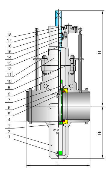 |
No. | Accessory name | Material |
| GB | |||
| 1 | Blow down stopple | 25 | |
| 2 | Body | WCB | |
| 3 | Gate disc | 16Mn+ENP | |
| 4 | Seat | 16Mn | |
| 5 | O-Ring | FPM | |
| 6 | Sealing ring | PTFE | |
| 7 | Valve stem nut | ZQAL9-4 | |
| 8 | Stem | 1Cr13 | |
| 9 | Packing | Graphite+1Cr18Ni9 | |
| 10 | Bonnet | WCB | |
| 11 | Stud | 35CrMo | |
| 12 | Nut | 45 | |
| 13 | O-Ring | FPM | |
| 14 | Bearing | Package | |
| 15 | To the ring of holding | 45 | |
| 16 | Six angle screws inside | 35 | |
| 17 | Key | 45 | |
| 18 | Switch indicator | PTFE+1Cr18Ni9 |
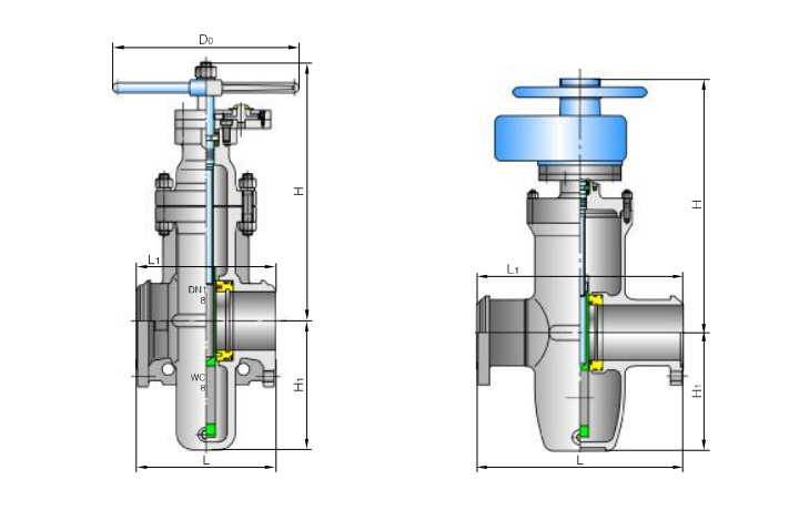
Model: (K)Z4(5、9B)4(6)7F PN0.4、0.6、1.0、1.6、2.5MPa PN2.0MPa API 6D Class150
| DN (mm) |
NPS (in) |
Flange | Butt welding | Hand-operated | Geared driving | Geared driving | Electric driving device | Electric driving device | ||||||
| L | L₁ | H₁ | H | D₀ | H₁ | H | D₀ | H₁ | H | D₀ | ||||
| 25 | 1 | 165 | - | 85 | 228 | 180 | - | - | - | - | - | - | - | - |
| 32 | 1¹/₄ | 165 | - | 103 | 231 | 180 | - | - | - | - | - | - | - | - |
| 40 | 1¹/2 | 178 | - | 115 | 240 | 250 | - | - | - | - | - | - | - | - |
| 50 | 2 | 178 | 216 | 130 | 255 | 250 | - | - | - | - | - | - | - | - |
| 65 | 2¹/₂ | 190 | 241 | 160 | 355 | 300 | - | - | - | - | - | - | - | - |
| 80 | 3 | 203 | 283 | 180 | 360 | 300 | - | - | - | - | - | - | - | - |
| 100 | 4 | 229 | 305 | 214 | 400 | 300 | - | - | - | - | - | - | - | - |
| 125 | 5 | 254 | 381 | 257 | 460 | 350 | - | - | - | - | - | - | - | - |
| 150 | 6 | 267 | 403 | 300 | 500 | 350 | - | - | - | - | - | - | - | - |
| 200 | 8 | 292 | 419 | 388 | 570 | 350 | - | - | - | - | - | - | - | - |
| 250 | 10 | 330 | 457 | 475 | 680 | 400 | 475 | 700 | 350 | 0 Type | 475 | 710 | 500 | SMC-03 |
| 300 | 12 | 356 | 502 | 547 | 750 | 450 | 547 | 870 | 350 | 0 Type | 547 | 880 | 305 | SMC-00 |
| 350 | 14 | 381 | 572 | 625 | 875 | 450 | 625 | 995 | 450 | 1 Type | 625 | 1015 | 305 | SMC-00 |
| 400 | 16 | 406 | 610 | 712 | 1000 | 500 | 712 | 1120 | 450 | 1 Type | 712 | 1130 | 305 | SMC-00 |
| 450 | 18 | 432 | 660 | 785 | 1130 | 500 | 785 | 1280 | 450 | 1 Type | 785 | 1360 | 305 | SMC-0 |
| 500 | 20 | 457 | 711 | 880 | 1200 | 600 | 880 | 1350 | 450 | 1 Type | 880 | 1430 | 305 | SMC-0 |
| 600 | 24 | 508 | 813 | 1045 | 1420 | 800 | 1045 | 1570 | 500 | 2 Type | 1045 | 1650 | 305 | SMC-1 |
| 700 | 28 | 610 | 914 | 1190 | 1650 | 800 | 1190 | 1800 | 500 | 2 Type | 1190 | 1910 | 305 | SMC-1 |
| 800 | 32 | 660 | 914 | 1360 | 1880 | 1000 | 1360 | 2040 | 500 | 2 Type | 1360 | 2140 | 305 | SMC-1 |
| 900 | 36 | 771 | 1016 | 1510 | 2100 | 1000 | 1510 | 2280 | 600 | 3 Type | 1510 | 2390 | 458 | SMC-2 |
| 1000 | 40 | 811 | - | 1715 | 2300 | 1200 | 1715 | 2480 | 600 | 3 Type | 1715 | 2590 | 458 | SMC-2 |
Model: (K)Z4(5、9B)4(6)7F PN0.4MPa PN5.0MPa API 6D Class300
| DN (mm) |
NPS (in) |
Flange | Butt welding | Hand-operated | Geared driving | Geared driving | Electric driving device | Electric driving device | |||||||
| L | |||||||||||||||
| GB | API | L₁ | H₁ | H | D₀ | H₁ | H | D₀ | H₁ | H | D₀ | ||||
| 25 | 1 | 165 | 165 | 165 | 85 | 238 | 180 | - | - | - | - | - | - | - | - |
| 32 | 1¹/₄ | 178 | 178 | 178 | 103 | 238 | 180 | - | - | - | - | - | - | - | - |
| 40 | 1¹/2 | 190 | 190 | 190 | 115 | 245 | 250 | - | - | - | - | - | - | - | - |
| 50 | 2 | 216 | 216 | 216 | 130 | 265 | 250 | - | - | - | - | - | - | - | - |
| 65 | 2¹/₂ | 241 | 241 | 241 | 160 | 365 | 300 | - | - | - | - | - | - | - | - |
| 80 | 3 | 283 | 283 | 283 | 180 | 375 | 300 | - | - | - | - | - | - | - | - |
| 100 | 4 | 305 | 305 | 305 | 214 | 420 | 300 | - | - | - | - | - | - | - | - |
| 125 | 5 | 381 | 381 | 381 | 257 | 480 | 350 | - | - | - | - | - | - | - | - |
| 150 | 6 | 403 | 403 | 403 | 300 | 540 | 350 | - | - | - | - | - | - | - | - |
| 200 | 8 | 419 | 419 | 419 | 388 | 610 | 350 | 388 | 710 | 350 | 0 Type | 388 | 720 | 305 | SMC-00 |
| 250 | 10 | 457 | 457 | 457 | 475 | 710 | 400 | 475 | 820 | 350 | 0 Type | 475 | 830 | 305 | SMC-00 |
| 300 | 12 | 502 | 502 | 502 | 547 | 810 | 450 | 547 | 900 | 450 | 1 Type | 547 | 910 | 305 | SMC-0 |
| 350 | 14 | 572 | 762 | 762 | 625 | 920 | 450 | 625 | 1015 | 450 | 1 Type | 625 | 1095 | 305 | SMC-0 |
| 400 | 16 | 610 | 838 | 838 | 712 | 1120 | 550 | 712 | 1150 | 450 | 1 Type | 712 | 1230 | 305 | SMC-0 |
| 450 | 18 | 660 | 914 | 914 | 785 | 1230 | 700 | 785 | 1300 | 500 | 2 Type | 785 | 1400 | 305 | SMC-1 |
| 500 | 20 | 711 | 991 | 991 | 880 | 1310 | 800 | 880 | 1370 | 500 | 2 Type | 880 | 1470 | 305 | SMC-1 |
| 600 | 24 | 787 | 1143 | 1143 | 1045 | 1520 | 1000 | 1045 | 1620 | 600 | 3 Type | 1045 | 1730 | 305 | SMC-1 |
Model: (K)Z4(5、9B)4(6)7F PN6.4MPa PN2.0MPa API 6D Class400
| DN (mm) |
NPS (in) |
Flange | Butt welding | Hand-operated | Geared driving | Geared driving | Electric driving device | Electric driving device | ||||||
| L | L₁ | H₁ | H | D₀ | H₁ | H | D₀ | H₁ | H | D₀ | ||||
| 50 | 2 | 216 | 250 | 158 | 265 | 300 | - | - | - | - | - | - | - | - |
| 65 | 2¹/₂ | 241 | 280 | 190 | 365 | 300 | - | - | - | - | - | - | - | - |
| 80 | 3 | 283 | 310 | 225 | 375 | 350 | - | - | - | - | - | - | - | - |
| 100 | 4 | 305 | 350 | 255 | 420 | 350 | - | - | - | - | - | - | - | - |
| 125 | 5 | 381 | 400 | 275 | 480 | 400 | - | - | - | - | - | - | - | - |
| 150 | 6 | 403 | 450 | 330 | 540 | 400 | - | - | - | - | - | - | - | - |
| 200 | 8 | 419 | 550 | 410 | 610 | 500 | 388 | 710 | 350 | 0 Type | 388 | 720 | 305 | SMC-0 |
| 250 | 10 | 457 | 650 | 490 | 710 | 500 | 475 | 820 | 350 | 0 Type | 475 | 830 | 305 | SMC-0 |
| 300 | 12 | 502 | 750 | 570 | 810 | 600 | 547 | 900 | 450 | 1 Type | 547 | 910 | 305 | SMC-0 |
| 350 | 14 | 762 | 850 | 625 | 920 | 600 | 625 | 1015 | 450 | 1 Type | 625 | 1095 | 305 | SMC-1 |
| 400 | 16 | 838 | 950 | 735 | 1120 | 700 | 712 | 1150 | 450 | 1 Type | 712 | 1230 | 305 | SMC-1 |
The increasing popularity of IoT devices has driven the demand for industrial valves. The integration of IoT sensors in industrial valves enables real-time monitorin...
A gate valve is an opening and closing component, and its movement direction is perpendicular to the fluid direction. A gate valve can only be fully opened and fully...
Ball valve, the opening and closing element (ball) is driven by the valve stem and rotates around the axis of the ball valve. It can also be used for fluid regulatio...