0086-577-67316655
fyv@fyvvalve.com
+8613588924788
Fangyuan Industrial Park, Anfeng Industrial Zone. Obei and Wenzhou, Zhejiang. China.
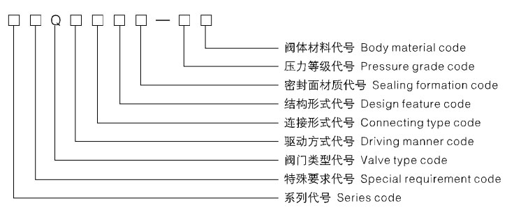
●Series code:The series code of our company is FY
●Special requirement code: K-Antisulphur type D-Low temperature type EX-Pole extending type M-Ground burying type
●Valve type code: Q-Ball valve
●Driving manner code: 3-Worm wheel and screw trensmission 6-Air driving 7-Hydrodynamic driving
8-Air-hydro operated 9-Electric driving 9e-Explosion electric driving
●Connecting type code: 1-The interior whorl joining 2-The other whorl joining 4-The flange joining
6-To welding joining 7-To inserting joining 8-The caliper joining
●Design feature code:1-Direct floating type 4—Floating type three direct links of Model L 5—Floating type three direct links of Model T
7-Direct regular type 8-Regular type Model T three direct links 9-Regular type Model L three direct links
●Sealing formation code: Y-Hard alloy F-Strengthen the polytetrafluoroethylene (PTFE) N-Nylon PPL-Counterpoint polyphenyl
●Pressure grade code: The 10 times of the nominal pressure MPa, pound grade io practical number
●Body material code: C-WCB I-WC6、ZG1Cr5Mo V-WC9、ZG20CrMoV P-CF8、ZG1Cr18Ni9Ti
R-CF8M、ZG1Cr18Ni12Mo2Ti S-CF3 L-CF3M F-LCB N-LC3
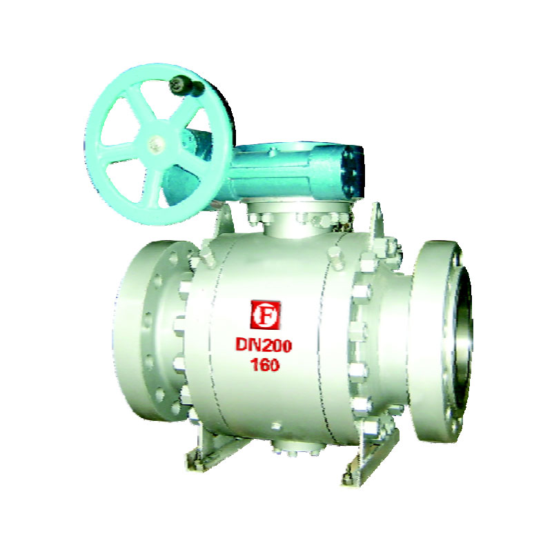
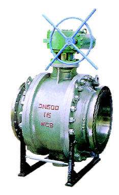
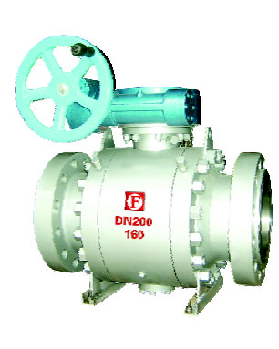
GB Trunnion Ball Valve
Design and Manufacture: GB/T19672、GB/T12237
Face to Face Dimension: GB/T12221、GB/T19672
Flange Connection Dimension: JB/T79、GB/T9113、HG20592
Test and Inspection: JB/T9092
Fire-safe Design: JB/T6899
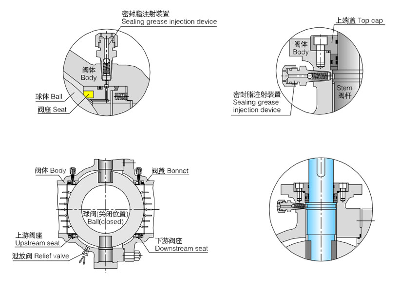
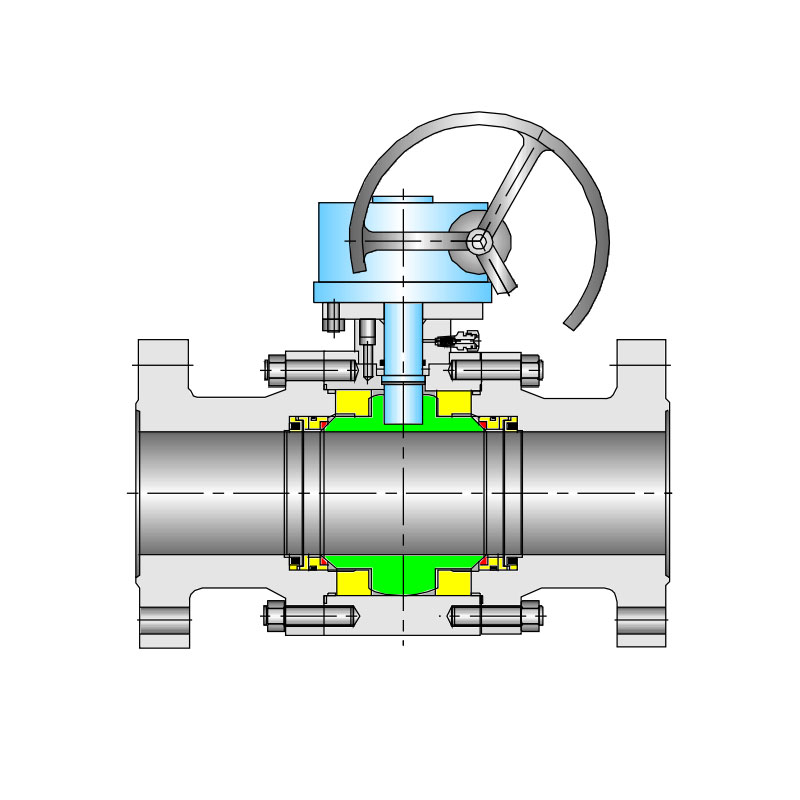
Urgent Grease Injection Device
According to customers' requirement the trunnion ball valve made by our company are provided with devices for urgent grease injection, which are on both the stem and seat for the trunnion ball valves of DN> 150mm (NPS6), and in the body cavity for the valve of DN<125mm. When the O ring of stem or the body seat ring is damaged due to accident, the medium leakage between body and stem can be prevented by injecting the sealing grease through the device.
Double-blockand Bleed Functions
In general, our company's trunnion ball valve features the front ball sealing design structure. Each seat of the ball valve can separately cut off the medium at both inlet and outlet of the valve to realize double-block functions. When the ball valve is close, body cavity and two of the body ends can be blocked with each other even if both the inlet and outlet are under pressure, when the medium left in the body cavity might be bled through the relief valve.
Blow-out proof stem
Blow-out proof structure is provited with for the stem. which is positioned by the up-end cap and screw, being guaranteed not to be blown-out by the medium even if at abnormal risen pressure in the cavity.
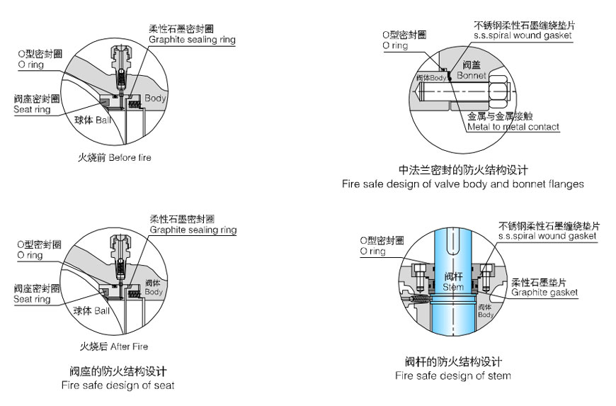
With the valve heated in a fire application, the non-metal material parts such as seat sealing ring of PTFE, O ring for the stem and sealing gasket for body and bonnet, might be damaged due to high temperature. Our company's special design of auxiliary metal to metal or the graphite seal is provided for the trunnion ball valve to effectively prevent both internal and external leakage of the valve. As required by customers, our company's fire safe design for the trunnion ball valve meets the requirement API 607, API 6Fa, BS6755 and JB/T 6899.
As the liquid medium left in the body cavity gasifies due to increased temperature, the pressure in the body cavity becomes abnormally higher, when the medium itself in the cavity would propel the seat and self-relieves the pressure to ensure the safety of valve.
According to some special working conditions andcustomers' requirement, our company is has provided the trunnion ball valve with the Bi-sealing design structure, i.e.seat sealing in front of the ball and seat sealing behind the ball, thus the reliable sealing of the valve is ensured because the valve can perform normally even if one of the effective sealing designs becomes lost due to the abnormal condition.
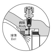
Regarding the seat in front of the ball, the piston effect formed by the area difference between D1 and D2, plus the pre-tightened force of a spring would cause the seat in front of the ball by the pressure difference of the medium before and after the valve to touch the ball closely to form the tightness, of which the sealing force will become bigger as the pressure difference gets higher.
Regarding the seat after the ball, the piston effect formed by the area difference between D2 and D3, plus the pretigh-tened force of a spring would cause the seat behind the ball to touch the ball closely to form the tightness, of which the sealing force willbecome bigger as the pressure difference gets higher.
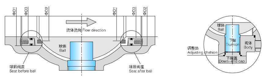
The ball of the trunnion ball valve gets close contact with each other through the trunnion, adjusting cushion and down-end cap, the passage of static electricity thus forms together with the valve, which may lead the static electricity caused by sparks generated by friction between the ball and seat during on and off performance to the ground to prevent the posible risk of fire or explosion.
Our company is has provided for trunnion ball valve with a mounting pad for fixing the actuators,such as worm gear, pneumatic, electric, hydraulic and pneumatic &hydraulic acturtors.
Valve models compiled per JB/T308 *compilation method of valve model"
The operation torque data of soft sealed trunnion ball valve in the following table are calculated based on normal temperature and clean medium. As selecting actuator, it is suggested that drive torque of actuator be more than 1.3 times the operation torque of ball valve at least. In case of high temperature and low temperature working conditions or unclean medium, it is possible that valve operation torque gets increased, which should be taken into full consideration as selecting actuators. Operation torque for metal to metal sealed trunnion ball valve is about 3~4 times that of soft sealed trunnion ball valve.
| NPS | DN | Operation torque of soft sealed trunnion ball valve N.m | |||||||||||
| Class150 PN20 |
Class300 PN50 |
Class600 PN110 |
Class900 PN150 |
Class1500 PN260 |
Class2500 PN420 |
PN16 | PN25 | PN40 | PN63 | PN100 | PN160 | ||
| 1 ¹/₂ | 40 | - | - | - | - | 100 | 160 | - | - | - | - | - | - |
| 2 | 50 | - | - | 70 | 100 | 155 | 250 | - | - | - | - | 70 | 105 |
| 2 ¹/₂ | 65 | - | - | 120 | 170 | 265 | 420 | - | - | - | - | 120 | 180 |
| 3 | 80 | - | - | 280 | 320 | 500 | 800 | - | - | - | - | 230 | 340 |
| 4 | 100 | 110 | 200 | 340 | 480 | 750 | 1200 | 100 | 140 | 170 | 240 | 340 | 500 |
| 5 | 125 | 180 | 290 | 550 | 780 | 1200 | 1900 | 160 | 220 | 260 | 350 | 550 | 820 |
| 6 | 150 | 340 | 480 | 800 | 1100 | 1700 | 2700 | 300 | 380 | 450 | 600 | 800 | 1150 |
| 8 | 200 | 500 | 850 | 1700 | 2400 | 3700 | 5900 | 450 | 630 | 750 | 1300 | 1700 | 2500 |
| 10 | 250 | 830 | 1400 | 2800 | 4000 | 6200 | 9900 | 750 | 1050 | 1250 | 2000 | 2800 | 4200 |
| 12 | 300 | 1400 | 2400 | 4200 | 5900 | 9100 | - | 1250 | 1750 | 2100 | 2900 | 4200 | 6200 |
| 14 | 350 | 2200 | 3100 | 5800 | 8100 | - | - | 2000 | 2600 | 2800 | 3700 | 5800 | - |
| 16 | 400 | 2600 | 4800 | 7500 | 10500 | - | - | 2350 | 3200 | 4300 | 5800 | 7500 | - |
| 18 | 450 | 3700 | 6100 | 9500 | - | - | - | 3300 | 4600 | 5500 | - | - | - |
| 20 | 500 | 4800 | 7500 | 11500 | - | - | - | 4300 | 6000 | 6800 | - | - | - |
| 24 | 600 | 8200 | 12000 | 16500 | - | - | - | 7400 | 10000 | 11000 | - | - | - |
| 26 | 650 | 9600 | 15000 | - | - | - | - | - | - | - | - | - | - |
| 28 | 700 | 12000 | 19000 | - | - | - | - | - | - | - | - | - | - |
| 30 | 750 | 14000 | 22000 | - | - | - | - | - | - | - | - | - | - |
| 32 | 800 | 16000 | 28000 | - | - | - | - | - | - | - | - | - | - |
| 36 | 900 | 20000 | 35000 | - | - | - | - | - | - | - | - | - | - |
 |
Design reference | GB |
| Design standard | GB/T 19672、GB/T 12237 | |
| Structural length | GB/T 12221 | |
| Flanged endsr | GB/T 9113、JB/T 79 | |
| Butt-welding ends | GB/T 12224 | |
| Test & inspection | JB/T 9092 |
Notes: The sizes of valve connecting flange and butt-welding terminas can be designed according to customer's requirement.
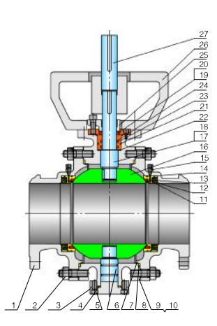 |
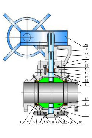
No. | Accessory name | Material |
| GB | |||
| 1 | The end covering | WCB | |
| 2 | Nut | 35 | |
| 3 | Bottom cover | WCB | |
| 4 | Gasket | PTFE,Graphite+stainless steel | |
| 5 | Screw | 35CrMo | |
| 6 | Put the valve stem** | 1Cr13 | |
| 7 | O Ring | NBR | |
| 8 | Gasket | PTFE,Graphite+stainless steel | |
| 9 | Body | WCB | |
| 10 | Blowdown is filled in | 25 | |
| 11 | Spring | 65Mn | |
| 12 | Seat* | 25 | |
| 13 | Sealing ring | PTFE | |
| 14 | O Ring | NBR | |
| 15 | Grease injection valve | Package | |
| 16 | Ball* | WCB+HCr | |
| 17 | Stem** | 1Cr13 | |
| 18 | Key | 45 | |
| 19 | Gasket | PTFE+stainless steel | |
| 20 | O Ring | NBR | |
| 21 | Packing case | 25 | |
| 22 | Screw | 35CrMo | |
| 23 | Packing seat | 1Cr13 | |
| 24 | Packing | PTFE;Carbon fibre;Soft graphite | |
| 25 | Packing gland | WCB | |
| 26 | Yoke | Q235A | |
| 27 | Connection set | 45 |
The material of this part about the anti-sulphur type valve is GB (1Cr18Ni9+Ni.P), ASTM(A182-304+Ni.P)
The material of this part about the anti-sulphur type valve is GB (1Cr18Ni9),ASTM(A276-321)
Major parts of the valve series and materials of sealing surface differ according to actual working condition and customer's special requirement.
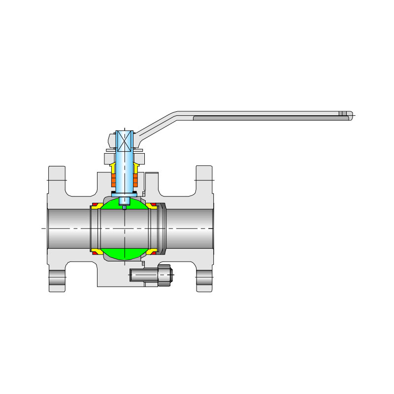
 |
Design reference | GB |
| Design standard | GB/T 19672、GB/T 12237 | |
| Structural length | GB/T 12221 | |
| Flanged endsr | GB/T 9113、JB/T 79 | |
| Butt-welding ends | GB/T 12224 | |
| Test & inspection | JB/T 9092 |
Notes: The sizes of valve connecting flange and butt-welding terminas can be designed according to customer's requirement.
 |
No. | Accessory name | Material |
| GB | |||
| 1 | Spring | Inconel x-750 | |
| 2 | Seat | 25 | |
| 3 | Sealing ring | PTFE | |
| 4 | O Ring | NBR | |
| 5 | Screw | 35CrMo | |
| 6 | Gasket | PTFE & Graphite | |
| 7 | Put the valve stem* | 1Cr13 | |
| 8 | Gasket | PTFE & Graphite | |
| 9 | Bottom cover | 25 | |
| 10 | Valve body,end | 25 | |
| 11 | Gasket | PTFE & Graphite | |
| 12 | O Ring | NBR | |
| 13 | Ball* | A105+HCr | |
| 14 | Slip the bearing | PTFE | |
| 15 | Stem** | 1Cr13 | |
| 16 | Grease injection valve | Package | |
| 17 | Gasket | PTFE & stainless steel | |
| 18 | Packing case | 25 | |
| 19 | Press and cover | 25 | |
| 20 | O Ring | NBR | |
| 21 | Yoke | Q235A | |
| 22 | Key | 45 | |
| 23 | Connection set | 45 | |
| 24 | Driving | Package |
The material of this part about the anti-sulphur type valve is GB (1Cr18Ni9+Ni.P),ASTM(A182-304+Ni.P)
The material of this part about the anti-sulphur type valve is GB (1Cr18Ni9),ASTM(A276-321)
Major parts of the valve series and materials of sealing surface differ according to actual working condition and customer's special requirement.
Model: (K)Q3(6、7、8、9)4(6)7F(Y、N、PPL)
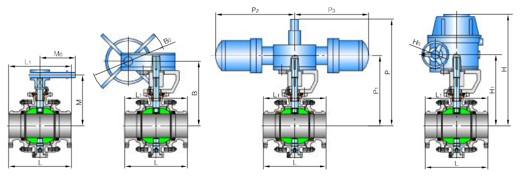
| Pressure | Nominal dimeter | Flange | Butt welding | Hand-operated | Worm gear worm | Air-operating and Fluid driving | Electric driving | |||||||||||
| mm | in | L | L₁ | M | M₀ | B | B₀ | Model | P | P₁ | P₂ | P₃ | Model | H | H₁ | H₀ | Model | |
| 1.6MPa | 50 | 2 | 179 | 216 | 107 | 230 | - | - | - | 270 | 174 | 89 | 181 | AG09 | - | - | - | - |
| 65 | 2 ¹/₂ | 191 | 241 | 125 | 400 | - | - | - | 380 | 248 | 148 | 257 | AG13 | - | - | - | - | |
| 80 | 3 | 203 | 283 | 152 | 400 | - | - | - | 390 | 258 | 148 | 257 | AG13 | - | - | - | - | |
| 100 | 4 | 229 | 305 | 178 | 650 | - | - | - | 480 | 322 | 287 | 287 | AW13 | - | - | - | - | |
| 125 | 5 | 356 | 381 | 300 | 1050 | - | - | - | 555 | 395 | 287 | 287 | AW13 | - | - | - | - | |
| 150 | 6 | 394 | 457 | 330 | 1050 | - | - | - | 665 | 457 | 378 | 378 | AW17 | 554 | 337 | 200 | SMC-04+H0BC | |
| 200 | 8 | 457 | 521 | - | - | 400 | 600 | B | 805 | 595 | 378 | 378 | AW17 | 600 | 382 | 200 | SMC-04+H1BC | |
| 250 | 10 | 533 | 559 | - | - | 495 | 600 | B | 840 | 630 | 378 | 378 | AW17 | 652 | 435 | 200 | SMC-04+H1BC | |
| 300 | 12 | 610 | 635 | - | - | 580 | 800 | C | 975 | 728 | 530 | 530 | AW20 | 761 | 480 | 280 | SMC-03+H2BC | |
| 350 | 14 | 686 | 762 | - | - | 625 | 800 | C | 1130 | 883 | 530 | 530 | AW20 | 771 | 520 | 280 | SMC-03+H2BC | |
| 400 | 16 | 762 | 838 | - | - | 670 | 800 | D | 1460 | 1154 | 680 | 680 | AW28 | 831 | 580 | 280 | SMC-00+H3BC | |
| 450 | 18 | 864 | 914 | - | - | 698 | 800 | D | 1530 | 1224 | 680 | 680 | AW28 | 921 | 670 | 305 | SMC-00+H3BC | |
| 500 | 20 | 914 | 991 | - | - | 840| | 800 | D | 1560 | 1294 | 680 | 680 | AW28 | 943 | 770 | 305 | SMC-0+H4BC | |
| 600 | 24 | 1067 | 1143 | - | - | 1050 | 800 | DA | 1145 | 915 | 1455 | 1455 | C1-355 | 1123 | 850 | 305 | SMC-0+H4BC | |
| 700 | 28 | 1245 | 1346 | - | - | 1100 | 800 | DA | 1160 | 930 | 1455 | 1455 | C1-355 | 1218 | 945 | 400 | SMC-1+H5BC | |
| 800 | 32 | 1372 | 1524 | - | - | 1150 | 800 | DB | 1460 | 1100 | 1665 | 1665 | C2-490 | 1328 | 1055 | 400 | SMC-2+H6BC | |
| 900 | 36 | 1524 | 1727 | - | - | 1230 | 800 | DB | 1540 | 1180 | 1665 | 1665 | C2-490 | 1696 | 1130 | 460 | SMC-2+H6BC | |
| 1000 | 40 | 1753 | 1956 | - | - | 1320 | 800 | DC | 1630 | 1280 | 1960 | 1960 | C3-600 | 1925 | 1240 | 460 | SMC-3+H6BC | |
| Pressure | Nominal dimeter | Flange | Butt welding | Hand-operated | Worm gear worm | Air-operating and Fluid driving | Electric driving | |||||||||||
| mm | in | L | L₁ | M | M₀ | B | B₀ | Model | P | P₁ | P₂ | P₃ | Model | H | H₁ | H₀ | Model | |
| 2.5MPa 4.0MPa |
50 | 2 | 216 | 216 | 107 | 230 | - | - | - | 270 | 210 | 148 | 181 | AG13 | - | - | - | - |
| 65 | 2 ¹/₂ | 241 | 241 | 125 | 400 | - | - | - | 380 | 250 | 148 | 257 | AG13 | - | - | - | - | |
| 80 | 3 | 283 | 283 | 152 | 400 | - | - | - | 390 | 295 | 287 | 287 | AW13 | - | - | - | - | |
| 100 | 4 | 305 | 305 | 178 | 650 | - | - | - | 455 | 325 | 287 | 287 | AW13 | - | - | - | - | |
| 125 | 5 | 381 | 381 | 300 | 1050 | - | - | - | 580 | 390 | 378 | 378 | AW17 | - | - | - | - | |
| 150 | 6 | 403 | 457 | 330 | 1050 | - | - | - | 595 | 390 | 378 | 378 | AW17 | 554 | 337 | 200 | SMC-04+H0BC | |
| 200 | 8 | 502 | 521 | - | - | 400 | 600 | B | 595 | 530 | 378 | 378 | AW17 | 600 | 382 | 200 | SMC-04+H0BC | |
| 250 | 10 | 568 | 559 | - | - | 495 | 600 | B | 736 | 700 | 530 | 530 | AW20 | 652 | 435 | 200 | SMC-04+H1BC | |
| 300 | 12 | 648 | 635 | - | - | 580 | 800 | C | 945 | 750 | 530 | 530 | AW20 | 761 | 480 | 280 | SMC-04+H1BC | |
| 350 | 14 | 762 | 762 | - | - | 625 | 800 | C | 995 | 885 | 680 | 680 | AW28 | 771 | 520 | 280 | SMC-03+H2BC | |
| 400 | 16 | 838 | 838 | - | - | 670 | 800 | D | 1280 | 975 | 680 | 680 | AW28 | 831 | 580 | 280 | SMC-03+H2BC | |
| 450 | 18 | 914 | 914 | - | - | 698 | 800 | D | 1480 | 1080 | 680 | 680 | AW28 | 921 | 670 | 305 | SMC-00+H3BC | |
| 500 | 20 | 991 | 991 | - | - | 840 | 800 | DA | 1555 | 1155 | 1455 | 1455 | C1-355 | 943 | 770 | 305 | SMC-00+H3BC | |
| 600 | 24 | 1143 | 1143 | - | - | 1050 | 800 | DB | 1380 | 930 | 1455 | 1455 | C1-355 | 1123 | 850 | 305 | SMC-0+H4BC | |
| 700 | 28 | 1346 | 1346 | - | - | 1100 | 800 | DC | 1430 | 980 | 1665 | 1665 | C2-490 | 1218 | 945 | 400 | SMC-0+H4BC | |
| 800 | 32 | 1524 | 1524 | - | - | 1150 | 800 | DC | 1750 | 1150 | 1665 | 1665 | C2-490 | 1328 | 1055 | 400 | SMC-1+H5BC | |
| 900 | 36 | 1727 | 1727 | - | - | 1230 | 800 | DD | 1540 | 1180 | 1960 | 1960 | C3-600 | 1696 | 1130 | 460 | SMC-2+H6BC | |
| 1000 | 40 | 2083 | 2083 | - | - | 1320 | 800 | DD | 1630 | 1280 | 1960 | 1960 | C3-600 | 1925 | 1240 | 460 | SMC-3+H6BC | |
| Pressure | Nominal dimeter | Flange | Butt welding | Hand-operated | Worm gear worm | Air-operating and Fluid driving | Electric driving | |||||||||||
| mm | in | L | L₁ | M | M₀ | B | B₀ | Model | P | P₁ | P₂ | P₃ | Model | H | H₁ | H₀ | Model | |
| 6.4MPa | 50 | 2 | 292 | 292 | 110 | 230 | - | - | - | 270 | 210 | 150 | 257 | AG13 | - | - | - | - |
| 65 | 2 ¹/₂ | 330 | 330 | 155 | 400 | - | - | - | - | - | - | - | - | - | - | - | - | |
| 80 | 3 | 356 | 356 | 200 | 400 | - | - | - | 520 | 295 | 287 | 287 | AW13 | - | - | - | - | |
| 100 | 4 | 406 | 406 | - | - | 235 | 600 | B | 640 | 325 | 287 | 287 | AW13 | - | - | - | - | |
| 150 | 6 | 495 | 495 | - | - | 300 | 800 | C | 730 | 390 | 378 | 378 | AW17 | 554 | 337 | 200 | SMC-04+H1BC | |
| 200 | 8 | 597 | 597 | - | - | 375 | 800 | C | 840 | 530 | 378 | 378 | AW20 | 600 | 382 | 200 | SMC-04+H1BC | |
| 250 | 10 | 673 | 673 | - | - | 445 | 800 | C | 1015 | 700 | 530 | 530 | AW20 | 652 | 480 | 200 | SMC-03+H2BC | |
| 300 | 12 | 762 | 762 | - | - | 515 | 800 | D | 1120 | 750 | 530 | 530 | AW28 | 761 | 520 | 280 | SMC-00+H3BC | |
| 350 | 14 | 826 | 826 | - | - | 550 | 800 | D | 1225 | 885 | 680 | 680 | AW28 | 771 | 594 | 280 | SMC-00+H3BC | |
| 400 | 16 | 902 | 902 | - | - | 615 | 800 | DA | 1480 | 1080 | 680 | 680 | C1-355 | 831 | 632 | 280 | SMC-0+H4BC | |
| 450 | 18 | 978 | 978 | - | - | 750 | 800 | DA | - | - | - | - | - | 921 | 670 | 305 | SMC-0+H4BC | |
| 500 | 20 | 1054 | 1054 | - | - | 810 | 800 | DB | 1480 | 1080 | 680 | 680 | C1-355 | 943 | 770 | 305 | SMC-1+H5BC | |
| 600 | 24 | 1232 | 1232 | - | - | 1050 | 800 | DC | 1365 | 915 | 1665 | 1665 | C2-490 | 1123 | 850 | 305 | SMC-3+H6BC | |
| 700 | 28 | 1397 | 1397 | - | - | 1100 | 800 | DD | 1430 | 980 | 1665 | 1665 | C2-490 | 1218 | 945 | 460 | SMC-3+H7BC | |
| 800 | 32 | 1651 | 1651 | - | - | 1180 | 800 | DD | - | - | - | - | - | 1328 | 1055 | 460 | SMC-4+H7BC | |
| 900 | 36 | 1880 | 1880 | - | - | 1275 | 800 | DH | - | - | - | - | - | 1815 | 1130 | 600 | SMC-4+H7BC | |
| 1000 | 40 | 2300 | 2300 | - | - | 1370 | 800 | DH | - | - | - | - | - | 1925 | 1240 | 600 | SMC-5+H6BC | |
| Pressure | Nominal dimeter | Flange | Butt welding | Hand-operated | Worm gear worm | Air-operating and Fluid driving | Electric driving | |||||||||||
| mm | in | L | L₁ | M | M₀ | B | B₀ | Model | P | P₁ | P₂ | P₃ | Model | H | H₁ | H₀ | Model | |
| 10.0MPa | 50 | 2 | 292 | 292 | 110 | 650 | - | - | - | 270 | 210 | 150 | 257 | AG13 | - | - | - | - |
| 65 | 2 ¹/₂ | 330 | 330 | 155 | 650 | - | - | - | - | - | - | - | - | - | - | - | - | |
| 80 | 3 | 356 | 356 | 200 | 650 | - | - | - | 520 | 295 | 287 | 287 | AW13 | - | - | - | - | |
| 100 | 4 | 432 | 432 | - | - | 235 | 600 | B | 640 | 480 | 287 | 287 | AW13 | - | - | - | - | |
| 150 | 6 | 559 | 559 | - | - | 300 | 800 | C | 730 | 520 | 378 | 378 | AW17 | 600 | 382 | 200 | SMC-04+H1BC | |
| 200 | 8 | 660 | 660 | - | - | 375 | 800 | C | 840 | 595 | 530 | 530 | AW20 | 652 | 480 | 200 | SMC-03+H2BC | |
| 250 | 10 | 787 | 787 | - | - | 445 | 800 | D | 1015 | 770 | 530 | 530 | AW20 | 761 | 520 | 280 | SMC-00+H3BC | |
| 300 | 12 | 838 | 838 | - | - | 515 | 800 | D | 1120 | 810 | 680 | 680 | AW28 | 771 | 594 | 280 | SMC-00+H3BC | |
| 350 | 14 | 889 | 889 | - | - | 550 | 800 | DA | 1225 | 1005 | 1445 | 1445 | C1-355 | 831 | 632 | 280 | SMC-0+H4BC | |
| 400 | 16 | 991 | 991 | - | - | 615 | 800 | DA | 1375 | 1155 | 1445 | 1445 | C1-355 | 921 | 670 | 305 | SMC-0+H4BC | |
| 450 | 18 | 1092 | 1092 | - | - | 750 | 800 | DB | - | - | - | - | - | 943 | 770 | 305 | SMC-1+H5BC | |
| 500 | 20 | 1194 | 1194 | - | - | 810 | 800 | DC | 1490 | 1210 | 1665 | 1665 | C2-490 | 1123 | 850 | 305 | SMC-3+H6BC | |
| 600 | 24 | 1397 | 1397 | - | - | 1050 | 800 | DD | 1615 | 1335 | 1665 | 1665 | C2-490 | 1218 | 945 | 400 | SMC-3+HGBC | |
| 700 | 28 | 1549 | 1549 | - | - | 1180 | 800 | DH | 1760 | 1410 | 1960 | 1960 | C3-600 | 1328 | 1055 | 400 | SMC-4+H7BC | |
| 800 | 32 | 1778 | 1778 | - | - | 1250 | 800 | DH | - | - | - | - | - | 1458 | 1135 | 600 | SMC-4+H7BC | |
| 900 | 36 | 2083 | 2083 | - | - | 1315 | 800 | DH | - | - | - | - | - | 1855 | 1170 | 600 | SMC-5+H7BC | |
| 1000 | 40 | 2337 | 2337 | - | - | 1420 | 800 | DH | - | - | - | - | - | 1960 | 1285 | 600 | SMC-5+H7BC | |
| Pressure | Nominal dimeter | Flange | Butt welding | Hand-operated | Worm gear worm | Air-operating and Fluid driving | Electric driving | |||||||||||
| mm | in | L | L₁ | M | M₀ | B | B₀ | Model | P | P₁ | P₂ | P₃ | Model | H | H₁ | H₀ | Model | |
| 16.0MPa | 50 | 2 | 368 | 368 | 220 | 650 | - | - | - | 520 | 295 | 287 | 287 | AW17 | - | - | - | - |
| 65 | 2 ¹/₂ | 419 | 419 | 240 | 650 | - | - | - | - | - | - | - | - | - | - | - | - | |
| 80 | 3 | 381 | 381 | 260 | 650 | - | - | - | 730 | 520 | 378 | 378 | AW17 | - | - | - | - | |
| 100 | 4 | 457 | 457 | - | - | 300 | 600 | B | 845 | 595 | 530 | 530 | AW20 | 600 | 382 | 200 | SMC-04+H1BC | |
| 150 | 6 | 610 | 610 | - | - | 365 | 800 | C | 1015 | 770 | 530 | 530 | AW20 | 761 | 520 | 280 | SMC-00+H3BC | |
| 200 | 8 | 737 | 737 | - | - | 395 | 800 | C | 1120 | 815 | 680 | 680 | AW28 | 771 | 594 | 280 | SMC-00+H3BC | |
| 250 | 10 | 838 | 838 | - | - | 505 | 800 | D | 1225 | 1005 | 1445 | 1445 | AW28 | 831 | 632 | 280 | SMC-0+H4BC | |
| 300 | 12 | 965 | 965 | - | - | 575 | 800 | D | 1375 | 1155 | 1445 | 1445 | C1-355 | 921 | 670 | 305 | SMC-0+H4BC | |
| 350 | 14 | 1029 | 1029 | - | - | 675 | 800 | DA | 1490 | 1210 | 1665 | 1665 | C1-355 | 943| | 770 | 305 | SMC-1+H5BC | |
| 400 | 16 | 1130 | 1130 | - | - | 765 | 800 | DB | 1615 | 1335 | 1665 | 1665 | C2-490 | 1123 | 850 | 305 | SMC-3+H6BC | |
| 450 | 18 | 1219 | 1219 | - | - | 870 | 800 | DC | 1760 | 1410 | 1960 | 1960 | C2-490 | 1218 | 945 | 400 | SMC-3+H6BC | |
| 500 | 20 | 1321 | 1321 | - | - | 895 | 800 | DD | 1760 | 1410 | 1960 | 1960 | C2-490 | 1328 | 1055 | 400 | SMC-4+H7BC | |
| 600 | 24 | 1549 | 1549 | - | - | 960 | 800 | DH | 1760 | 1410 | 1960 | 1960 | C3-600 | 1458 | 1135 | 600 | SMC-4+H7BC | |
| 700 | 28 | 1780 | 1700 | - | - | 1210 | 800 | DH | - | - | - | - | - | 1904 | 1180 | 600 | SMC-5+H7BC | |
| 800 | 32 | 2050 | 1780 | - | - | 1290 | 1000 | DJ | - | - | - | - | - | 1984 | 1260 | 600 | SMC-5+H7BC | |
| Pressure | Nominal dimeter | Flange | Butt welding | Hand-operated | Worm gear worm | Air-operating and Fluid driving | Electric driving | |||||||||||
| mm | in | L | L₁ | M | M₀ | B | B₀ | Model | P | P₁ | P₂ | P₃ | Model | H | H₁ | H₀ | Model | |
| 25.0MPa | 50 | 2 | 368 | 368 | 220 | 650 | 220 | 600 | A | 520 | 295 | 287 | 287 | AW17 | - | - | - | - |
| 65 | 2 ¹/₂ | 419 | 419 | 245 | 650 | 245 | 600 | A | 730 | 520 | 378 | 378 | AW17 | - | - | - | - | |
| 80 | 3 | 470 | 470 | 260 | 650 | 260 | 600 | B | 845 | 595 | 530 | 530 | AW17 | 655 | 480 | 200 | SMC-04+H1BC | |
| 100 | 4 | 546 | 546 | - | - | 300 | 600 | B | 1015 | 770 | 530 | 530 | AW20 | 765 | 520 | 280 | SMC-04+H1BC | |
| 150 | 6 | 705 | 705 | - | - | 365 | 800 | C | 1120 | 815 | 680 | 680 | AW28 | 775 | 595 | 280 | SMC-00+H3BC | |
| 200 | 8 | 832 | 832 | - | - | 475 | 800 | D | 1125 | 1005 | 1445 | 1445 | AW28 | 835 | 635 | 280 | SMC-00+H3BC | |
| 250 | 10 | 991 | 991 | - | - | 580 | 800 | D | 1375 | 1155 | 1445 | 1445 | C1-355 | 925 | 670 | 305 | SMC-0+H4BC | |
| 300 | 12 | 1130 | 1130 | - | - | 700 | 800 | DA | 1490 | 1210 | 1665 | 1665 | C1-355 | 945 | 770 | 305 | SMC-0+H4BC | |
| 350 | 14 | 1257 | 1257 | - | - | 765 | 800 | DB | 1615 | 1335 | 1665 | 1665 | C2-490 | 1125 | 850 | 305 | SMC-1+H5BC | |
| 400 | 16 | 1384 | 1384 | - | - | 835 | 800 | DC | 1760 | 1410 | 1960 | 1960 | C2-490 | 1220 | 945 | 400 | SMC-3+H6BC | |
Note: The face to face dimension and connecting flange of a diameter reduced valve are per the non-reducing norms; the sizes of both valve height and actuator are reduced by one norm size.
The increasing popularity of IoT devices has driven the demand for industrial valves. The integration of IoT sensors in industrial valves enables real-time monitorin...
A gate valve is an opening and closing component, and its movement direction is perpendicular to the fluid direction. A gate valve can only be fully opened and fully...
Ball valve, the opening and closing element (ball) is driven by the valve stem and rotates around the axis of the ball valve. It can also be used for fluid regulatio...